MeshInspector features a range of Select tools to choose objects or their elements for inspection and further actions. As such, it supports selection at two levels: both object-level selection for whole items and primitive-level selection for triangles (meshes) and points (point clouds).

Select Objects
Clicking Select Objects enables object-level selection for inspection and manipulation. You can select an object in two ways:
-
Click the object directly in the scene.
-
Click its name in the top-left object list.
Use this mode when you need to move, inspect, hide or show, or apply tools to entire objects rather than individual geometry elements.
Select Primitives
Clicking Select Primitives enables primitive-level selection. Use this tool when you need fine-grained selection for detailed inspection, cleanup, segmentation, or precise editing.
Selection Modes in Select Primitives
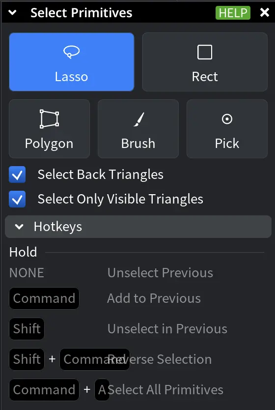
In the Select Primitives window, choose a selection mode to define how primitives are picked:
-
Lasso selects primitives inside a freeform curve you draw.
-
Rect selects primitives inside a rectangular area you drag.
-
Polygon selects primitives inside a custom polygon you define by clicking its vertices.
-
Brush selects primitives along a brush stroke you draw over the target area.
-
Pick selects individual primitives by clicking them directly.
Selection Settings in Select Primitives
Additional options refine primitive selection behavior:
-
Select Back Triangles includes triangles oriented away from the camera.
-
Select Only Visible Triangles limits selection to visible triangles, while also not including triangles occluded by other geometry.
Modifier Keys
Modifier keys change how the current selection is updated:
-
None replaces the selection (unselects the previous elements).
-
CTRL (or Command) adds primitives to the current selection.
-
SHIFT removes primitives from the current selection.
-
SHIFT + CTRL (or Command) reverses the selection.
-
CTRL (or Command) + A selects all primitives in the currently selected objects.
Additional Tools in Select Primitives
A dropdown menu provides extra primitive-selection options for specialized workflows.
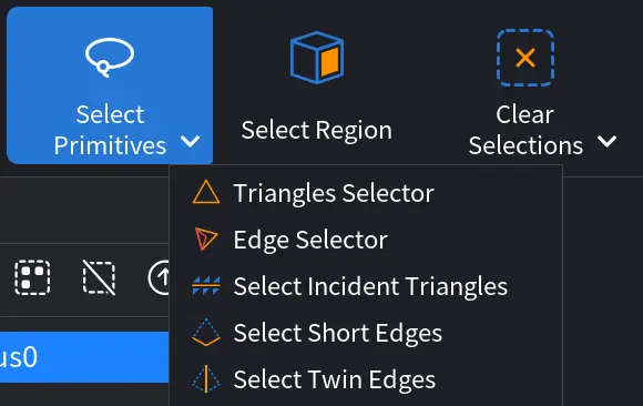
Triangles Selector
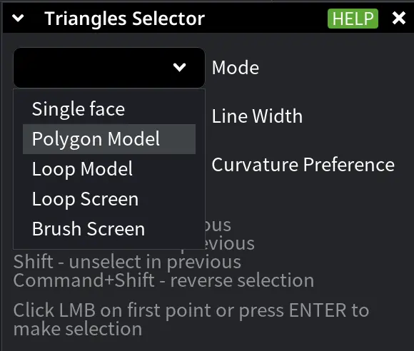
Clicking Triangles Selector opens a dedicated panel for selecting triangles on mesh surfaces using different selection modes. These modes allow you to define selection boundaries directly on the model or in screen space, depending on the task. Use the Mode dropdown to choose how triangles are selected.
Selection Modes in Triangles Selector
-
Single Face selects a single triangle under the mouse cursor. Use this mode for precise, element-by-element inspection or correction.
-
Polygon Model defines a selection boundary directly on the mesh surface by clicking a sequence of points. The selection follows the surface topology.
Additional settings:
-
Line Width defines the width of the selection boundary drawn on the surface.
-
Curvature Preference controls how the boundary follows the surface:
-
Geodesic follows the shortest path along the surface.
-
Convex favors outward-curving regions.
-
Concave favors inward-curving regions.
-
-
-
Loop Model defines a continuous selection boundary on the mesh surface by holding the mouse button and moving the cursor. The same Line Width and Curvature Preference options apply as in Polygon Model.
-
Loop Screen defines a closed selection loop in screen space by holding the mouse button and drawing the loop.
Additional options:
-
Select Back Triangles.
-
Select Only Visible.
-
-
Brush Screen selects multiple triangles by dragging a brush over the screen.
Additional options:
-
Brush Radius controls the size of the selection brush.
-
Select Back Triangles.
-
Select Only Visible.
-
Modifier Keys (Where Applicable)
Modifier keys change how the new selection interacts with the existing one. Hold:
-
None replaces the previous selection.
-
CTRL (or Command) adds triangles to the current selection.
-
SHIFT removes triangles from the current selection.
-
SHIFT + CTRL (or Command) reverses the selection.
Click the left mouse button (LMB) on the first point or Press ENTER to finalize the selection.
Edge Selector
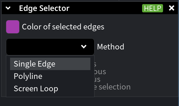
Clicking Edge Selector enables selection of mesh edges for inspection and further operations.
Colors in Edge Selector
Use Color of selected edges to customize how selected edges are displayed. Clicking this option opens a color picker. The color picker shows both the Current and Original colors for easy comparison. You can modify the Current color, while the Original color remains unchanged as a reference.
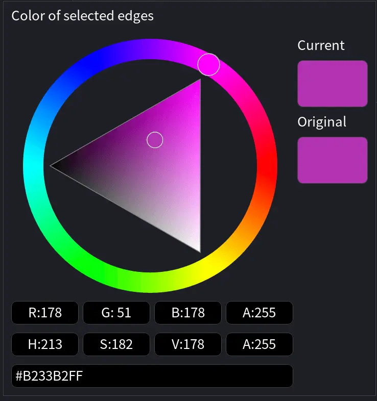
For precise adjustments, the panel displays RGBA (Red, Green, Blue, Alpha) values as well as HSV (Hue, Saturation, Value) values. You can also enter a specific HEX color code directly.
Modes in Edge Selector
There are three methods for selecting edges:
Single Edge selects a single edge under the mouse cursor with one click. Use this method for precise, edge-by-edge inspection or editing.
Polyline selects a connected polyline of edges by clicking successive points or by dragging the mouse along the surface.
Additional settings:
-
Curvature Preference controls how the polyline follows the surface:
-
Geodesic follows the shortest path along the surface.
-
Convex favors outward-curving regions.
-
Concave favors inward-curving regions.
-
Screen Loop uses a lasso-style selection drawn in screen space to select all edges inside the loop.
Additional options:
-
Include backfaces includes edges located on the reverse side of the mesh.
-
Include only visible limits selection to edges visible from the current view.
-
Include boundaries ensures that mesh boundary edges incident to the selected edges are also included.
Modifier Keys (Where Applicable)
Modifier keys change how the current edge selection is updated:
-
None replaces the previous selection.
-
CTRL (or Command) adds edges to the current selection.
-
SHIFT removes edges from the current selection.
-
SHIFT + CTRL (or Command) reverses the selection.
Select Incident Triangles
Clicking Select Incident Triangles, available once edges have been selected, selects all triangles incident to the currently selected edges.
Select Short Edges
Clicking Select Short Edges selects all edges whose length is less than or equal to a specified value. To use this feature, enter the desired threshold in the Max Edge Length field, then click Select to highlight all edges that meet the criterion. Use this option to identify and work with short edges during mesh inspection, cleanup, or optimization.
Select Twin Edges
Clicking Select Twin Edges locates pairs of vertices that are located very close to each other, which is often a sign of degenerate or redundant geometry. A distance threshold (in millimeters) defines how close vertex pairs must be to qualify. Once set, clicking Select highlights the corresponding edges associated with these vertex pairs. Use this feature to identify and remove degeneracies, improving overall mesh quality and geometric accuracy.
Select Region Workflow
Select Region performs smart region selection on a mesh by using user-defined seed triangles. You mark a set of triangles. Initially, these will be highlighted in red. After that you decide whether these belong to the desired region (they will be highlighted in green). Also, you may decide what triangles should not belong to the region (and they will be highlighted in grey).
Based on these seeds, the tool computes an optimal boundary between the region and the not-region by minimizing a metric along the boundary.
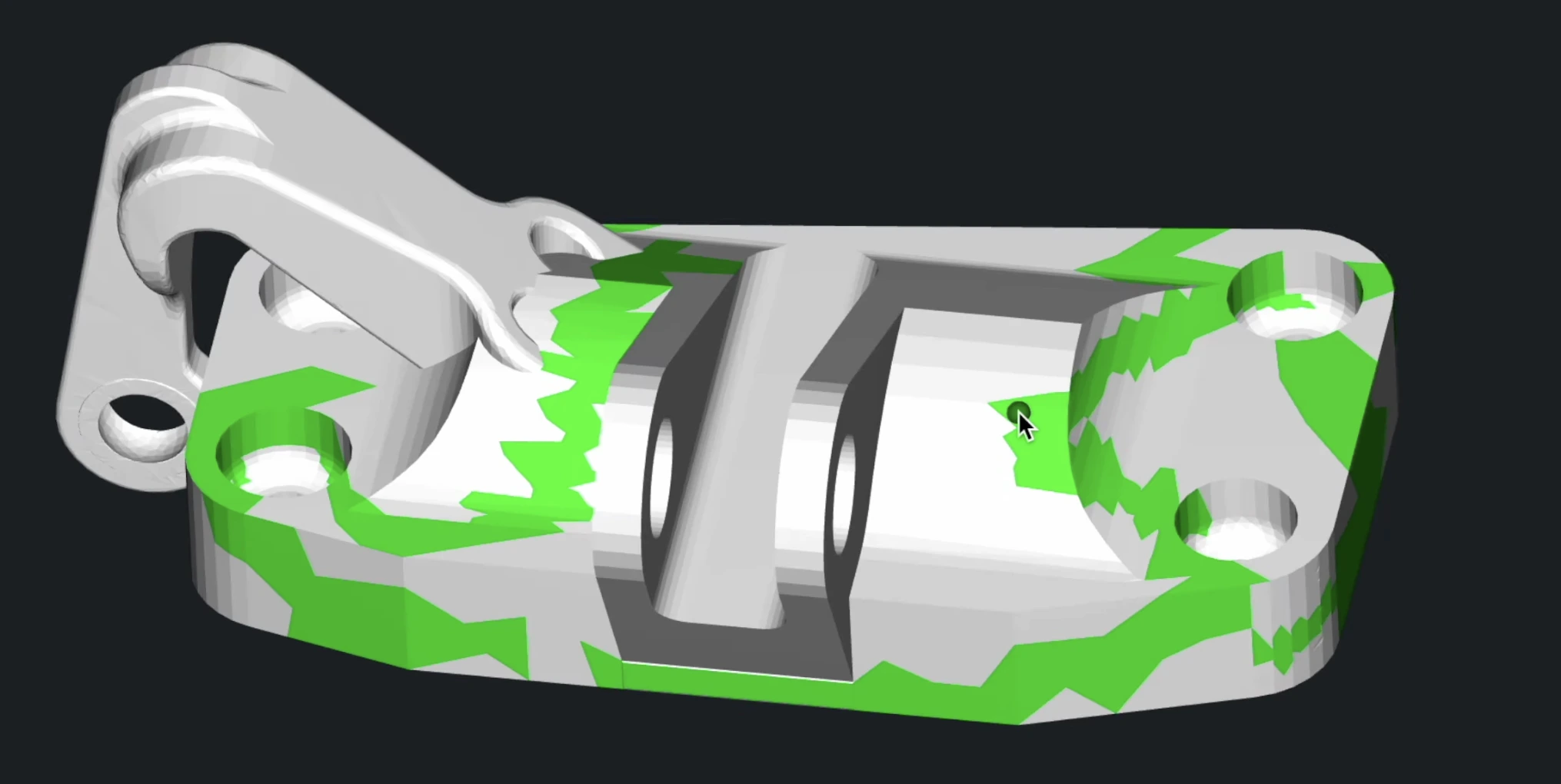
This approach allows precise isolation of regions on complex surfaces, even when the boundary is not explicitly drawn.
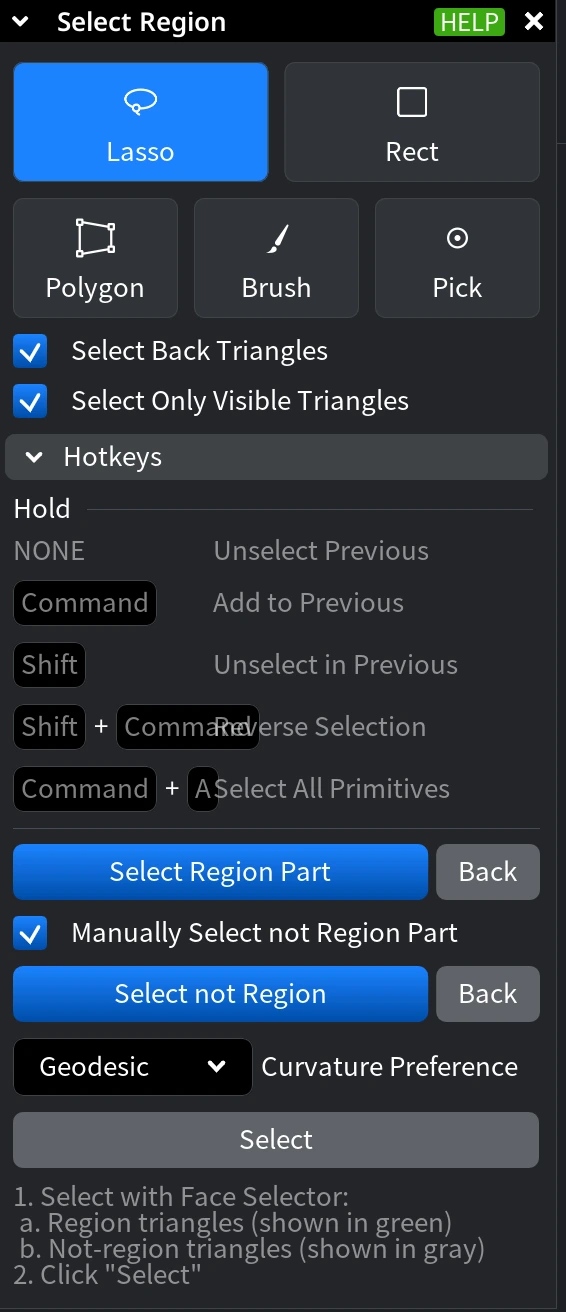
Step 1. Choose a Selection Mode
Start the workflow by selecting triangles that belong to the intended region using one of the available selection modes.
- Lasso enables freehand selection by drawing around an area.
- Rect selects all triangles within a dragged rectangular area.
- Polygon selects triangles inside a manually defined polygon.
- Brush enables paint-style selection with an adjustable radius.
- Pick selects individual triangles with a single click.
Step 2. Adjust Selection Behavior
-
Select Back Triangles includes triangles located on the hidden side of the mesh.
-
Select Only Visible Triangles limits selection to triangles visible from the current view.
When using Brush, you can also adjust the Brush Radius to control the size of the painted area.
Using Modifier Keys (Where Applicable)
While selecting triangles, modifier keys control how the current selection is updated:
-
None clears the previous selection.
-
CTRL (or Command) adds triangles to the current selection.
-
SHIFT removes triangles from the current selection.
-
SHIFT + CTRL (or Command) reverses the selection.
-
CTRL (or Command) + A selects all primitives.
Use these keys to incrementally build the set of triangles that define the region.
Step 3. Define Region Seeds
Once the desired triangles are selected, click Select Region Part to convert them into region seeds.
Region seeds are displayed in green and define the area of interest on the mesh.
This step is mandatory, i.e., the region cannot be computed until region seeds are defined.
Step 4. Define the Not-Region (When Applicable)
You can also specify triangles that should explicitly not belong to the region:
-
Enable Manually Select not Region to manually select not-region triangles.
-
Manually selected not-region triangles are displayed in gray.
If Manually Select not Region Part is disabled, MeshInspector automatically determines the not-region based on the defined region seeds.
Step 5. Uncertainty Distance and Curvature Preference in Select Region
When computing the boundary between the region and the not-region, Uncertainty Distance and Curvature Preference control how the boundary is placed and how it follows the mesh surface.
Uncertainty Distance defines the distance threshold between the user-selected region part and the automatically determined not-region part. Use Uncertainty Distance to balance boundary precision and robustness, especially when the separation between region and not-region is not clearly defined or when working with scanned meshes.
Curvature Preference defines how the boundary is traced along the mesh surface when multiple valid boundary paths are possible.
This setting influences which paths are favored during boundary computation:
-
Geodesic selects the shortest possible boundary path along the surface.
-
Convex prefers boundary paths that pass through convex regions of the mesh.
-
Concave prefers boundary paths that pass through concave regions of the mesh.
Curvature Preference allows you to control how tightly or loosely the computed region follows surface features, particularly on complex or highly curved geometry. Combined with Uncertainty Distance, it provides fine-grained control over both the position and shape of the computed region boundary.
Step 6. Finalize Your Region Selection flow
Click 'Select' to finalize the process.
Clear Selections
Clicking Clear Selections removes all currently selected triangles in meshes and points in point clouds.
Clear Selected Edges
Clicking Clear Selected Edges, available via the dropdown located next to Clear Selection, removes currently selected mesh edges.
Delete Selected
Clicking on Delete Selected removes the currently selected areas from objects.
Inverse Selection
Clicking Inverse Selection inverts the current selection in meshes or point clouds: selected triangles or points become unselected, and unselected ones become selected.
Grow/Shrink Selected
Clicking Grow/Shrink Selected allows you to expand (dilate) or contract (erode) the current selection by a specified distance. Clicking the tool opens a panel with the following settings:
-
Dilation Distance controls how much the selection expands outward.
-
Erosion Distance controls how much the selection contracts inward.
The following actions are available:
-
Dilate expands the selection by the specified dilation distance.
-
Erode shrinks the selection by the specified erosion distance.
-
Dilate & Erode expands the selection first, then contracts it.
-
Erode & Dilate contracts the selection first, then expands it.
Grow/Shrink Selected Edges
Clicking Grow/Shrink Selected Edges, available from the dropdown next to Grow/Shrink Selected, opens a panel with controls for expanding or contracting the current edge selection.
-
Distance Field defines how much the selection grows or shrinks along the edges. The value is specified in millimeters:
-
Positive values expand the selection.
-
Negative values shrink the selection.
-
-
Apply applies the specified grow or shrink operation to the selected edges.
Expand Selection
Clicking Expand Selection adds one additional layer of triangles to the current selection.
Smart Expand
Clicking Smart Expand, available from the dropdown next to Expand Selection, expands the selection based on planar or smooth regions of the mesh. Selecting this option opens a panel with an Expansion slider, allowing you to control how far the selection expands.
Expand Selected Edges
Clicking Expand Selected Edges, available from the dropdown next to Expand Selection, adds one additional topological layer of edges to the current edge selection. Each use expands the selection by including edges adjacent to the currently selected ones. This option applies only to edge selections and is useful for gradually extending edge-based selections along the mesh topology.
Shrink Selection
Clicking Shrink Selection removes one topological layer of triangles from the boundary of the current triangle selection.
Shrink Selected Edges
Clicking Shrink Selected Edges, available from the dropdown next to Shrink Selection, removes one topological layer of edges from the boundary of the current edge selection.
Selection to Object
Clicking Selection to Object creates a new object from the currently selected elements of the active mesh. This tool extracts the selection into a separate object of the same type as the source object. For meshes, the new object is created from the selected triangles; for point clouds, it is created from the selected points. The original object remains unchanged, while the selected part becomes an independent object in the scene hierarchy. Use Selection to Object when you need to isolate a portion of geometry for separate inspection, editing, repair, or export without modifying the original mesh.
Select by Area
Select by Area allows you to select triangles based on their surface area relative to the total area of the object. This tool is useful for isolating very small or very large triangles, for example when cleaning up noise, degeneracies, or uneven tessellation. When activated, the Select by Area panel provides the following controls:
Scalar Type in Select by Area
Defines how the area threshold is interpreted:
-
Percentage compares triangle areas as a percentage of the total surface area of the object.
-
Absolute compares triangle areas using an absolute value in square millimeters.
Compare Type in Select by Area
Defines how triangle areas are compared against the specified threshold:
-
Less selects triangles with an area smaller than the specified value.
-
Greater selects triangles with an area larger than the specified value.
Area in Select by Area
Specifies the threshold used for comparison. The value is interpreted either as a percentage or as an absolute area, depending on the selected Scalar Type.
After setting the desired parameters, MeshInspector highlights all triangles that match the selected criteria, allowing you to further refine, modify, or process the selection using other selection and editing tools.
Select Component
Clicking Select Component allows you to select an entire connected component of a mesh by clicking on any triangle that belongs to it. A connected component is a group of triangles that are topologically connected to each other, with no gaps or disconnections.
When the tool is active, clicking on a triangle selects the whole component it belongs to. A control panel appears, and modifier keys can be used to refine the selection.
Modifier Keys (Where Applicable)
-
None replaces (unselects) the previous selection.
-
CTRL (or Command) adds the clicked component to the current selection.
-
SHIFT removes the clicked component from the current selection.
-
SHIFT + CTRL (or Command) reverses the selection state of the clicked component.
Select Component is useful for quickly isolating or removing parts of a mesh. For example, if a model contains multiple disjoint fragments, you can select an entire fragment with a single click and then delete it, duplicate it, or process it independently. You can also combine it with Inverse Selection to operate on everything except the chosen component.
Select Largest Component
Clicking Select Largest Component, available from the dropdown next to Select Component, automatically selects the largest connected component in the mesh, based on its size, without requiring a manual click. This is especially useful when working with imported or scanned models that contain small stray fragments, noise, or artifacts. With a single action, you can isolate the main body of the mesh and remove all smaller disconnected components.
Expand to Components
Clicking Expand to Components expands the current triangle selection to include entire connected mesh components that intersect with the selection.
When activated, the tool analyzes the selected triangles and treats the surrounding connected regions as components, using selected edges as component boundaries. As a result, any component that contains at least part of the current selection becomes fully selected.
This operation is useful when you initially select only a fragment of geometry but want to promote that partial selection to the full connected part of the mesh. For example, after selecting a few triangles on a feature or fragment, Expand to Components allows you to quickly select the entire connected section without manually selecting all of its triangles.
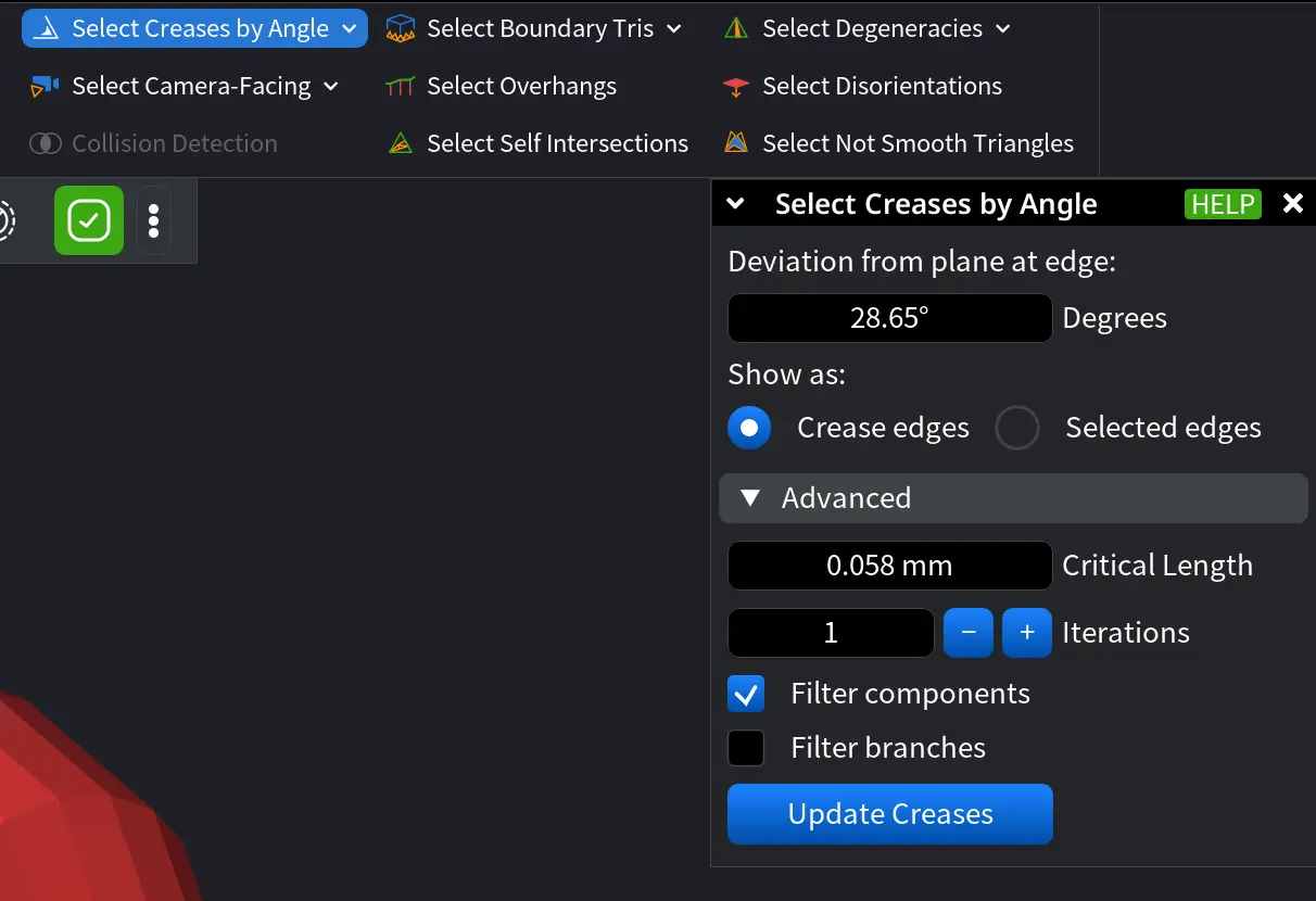
Select Creases by Angle
Clicking Select Creases by Angle automatically detects and selects creased edges based on the angle deviation between adjacent triangles. This helps identify sharp features, ridges, and geometric discontinuities on a mesh.
When activated, the tool opens a settings panel where you can adjust parameters that control crease detection and filtering.
Deviation from plane at edge defines the angle threshold (in degrees) used to detect creases. Edges where adjacent triangles deviate by more than this angle are considered creases.
Show as:
-
Crease edges highlights detected creases visually without changing the current selection.
-
Selected edges converts detected creases into an active edge selection.
Advanced settings in Select Creases by Angle
-
Critical Length defines the minimum edge length used when filtering crease components or branches.
-
Iterations specifies how many times the crease detection process is applied, allowing the result to be refined iteratively.
-
Filter components, when enabled, excludes connected crease components whose total edge length is below the Critical Length.
-
Filter branches, when enabled, excludes individual crease branches shorter than the Critical Length.
Click Update Creases to apply the current parameters and refresh the detected creases.
The Select Creases by Angle tool is especially useful when working with CAD-derived or mechanically precise geometry, where sharp edges and feature boundaries must be identified accurately. It supports workflows such as mesh cleanup, feature isolation, reverse engineering, and preparation for downstream operations like analysis or manufacturing.
Swap Creases / Edges
Clicking Swap Creases / Edges, available from the dropdown next to Select Creases by Angle, swaps the current selection of creases and edges: selected edges become creases, and selected creases become regular edges. This operation works only when there is an explicit selection of edges or creases in the mesh.
Select Camera-Facing
Clicking Select Camera-Facing automatically adds to the selection all triangles whose normals face the camera, even if other parts of the mesh partially or fully occlude them. This tool is useful for quickly selecting surfaces based on viewing direction.
Unselect Camera-Facing
Clicking Unselect Camera-Facing, available from the dropdown next to Select Camera-Facing, removes from the selection all triangles facing the camera, regardless of whether they are fully visible or occluded by other geometry. This allows quick refinement of selections when working with complex models or cleaning up visible regions.
Collision Detection
Clicking Collision Detection activates the tool for identifying intersecting triangles between two selected meshes. This feature is useful for detecting overlaps in 3D models, ensuring proper alignment, and avoiding unintended intersections.
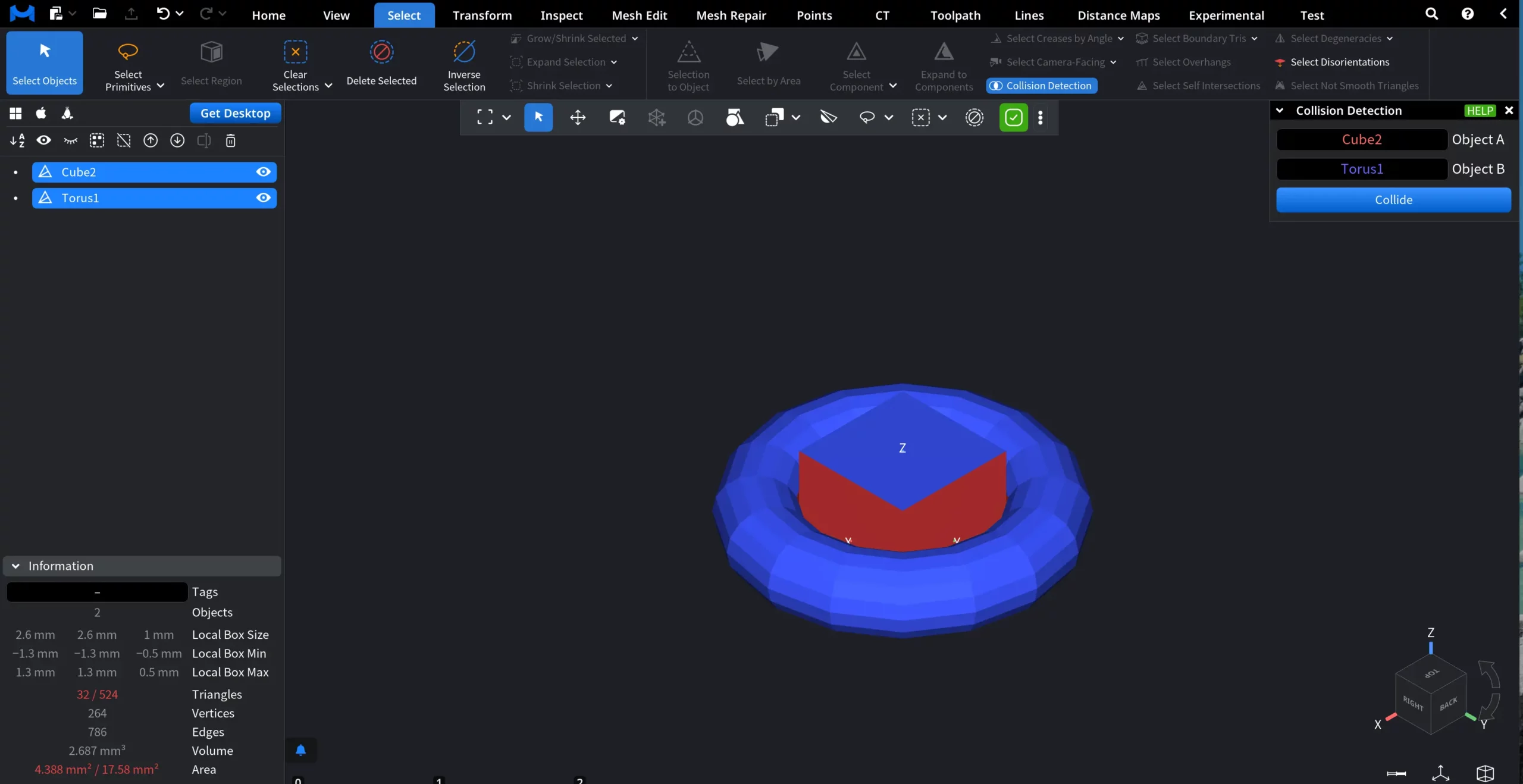
To use the tool:
-
Select two meshes: one as Object A and the other as Object B. Collision detection works only when two distinct objects are selected.
-
Click Collide to analyze the intersection. The tool highlights triangles where the meshes overlap.
Select Boundary Tris (“Tris” is for Triangles)
Clicking Select Boundary Tris adds to the selection all triangles that lie on the boundary of the mesh (i.e., triangles adjacent to open edges). This is useful for identifying holes, open borders, or incomplete areas in scanned or imported meshes. Once selected, boundary triangles can be further expanded, shrunk, or processed to help repair or smooth the mesh perimeter.
Select Boundary Edges
Clicking Select Boundary Edges, available from the dropdown next to Select Boundary Tris, adds to the selection all edges that lie on the boundary of the mesh (edges belonging to only one triangle). This is especially useful for detecting open contours, holes, or non-watertight geometry.
Select Overhangs
Clicking Select Overhangs detects and selects overhanging triangles—areas of the mesh that extend outward and may cause manufacturing or printing issues due to insufficient support. This tool is useful for identifying unsupported geometry and evaluating design feasibility.
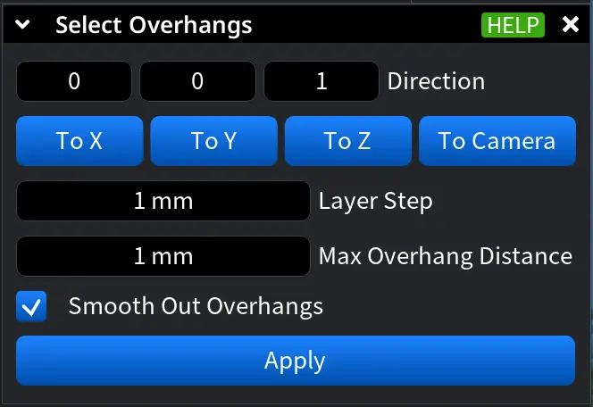
When activated, a settings panel appears with the following options:
-
Direction defines the reference direction used to detect overhangs:
-
To X, To Y, To Z analyze overhangs relative to the corresponding global axis.
-
To Camera analyzes overhangs relative to the current camera view.
-
-
Layer Step defines the distance between layers during the analysis. Smaller values result in finer, more detailed overhang detection.
-
Max Overhang Distance sets the maximum allowed overhang distance within a single layer. Triangles exceeding this value are classified as overhangs.
-
Smooth Out Overhangs, when enabled, removes small overhang artifacts, keeping only meaningful overhang regions in the selection.
After adjusting the parameters, click Apply to update the selection based on the specified criteria.
Select Self-Intersections
Clicking Select Self-Intersections identifies and selects triangles that intersect with other triangles within the same mesh. This tool helps detect and resolve problematic geometry that can cause issues in rendering, simulation, or manufacturing.
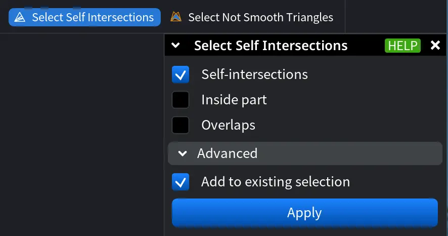
The tool provides several filtering options:
-
Self-Intersections selects triangles that geometrically intersect with other triangles in the mesh.
-
Inside Part selects triangles located inside the mesh volume rather than on its outer boundary.
-
Overlaps selects triangles that have nearby triangles with opposite orientation, which may indicate overlapping surfaces or inverted geometry.
Enabling Add to Existing Selection ensures that newly detected intersections are added to the current selection instead of replacing it. Clicking Apply runs the detection and updates the selection based on the chosen criteria.
Select Degeneracies
Clicking on Select Degeneracies detects and selects degenerate triangles in a mesh—triangles with extremely poor aspect ratios that may cause issues in rendering, simulation, or manufacturing.
When activated, a settings panel appears with the following options:
-
Min Aspect Ratio defines the minimum aspect ratio a triangle must have to be considered degenerate. Higher values select more severely distorted triangles, while lower values include a broader range of potential degeneracies.
-
Boundary Only, when enabled, limits the selection to degenerate triangles located on the boundary of the mesh.
Use Select Degeneracies to quickly identify problematic geometry such as long, thin, or collapsed triangles, helping improve mesh quality before further processing, analysis, or export.
Select Outer Layer
Clicking Select Outer Layer, available from the dropdown next to Select Degeneracies, automatically selects all triangles that belong to the outer layer of a double-layer mesh.
This tool is designed for meshes that contain two layers:
-
One layer with normals oriented outward, and
-
Another layer with normals oriented inward.
Select Outer Layer analyzes triangle orientations and identifies the layer facing outward, selecting all triangles that form the external surface of the model.
This is especially useful for:
-
Separating inner and outer shells in scanned or reconstructed meshes.
-
Cleaning up double-layer geometry.
-
Preparing meshes for manufacturing, simulation, or surface-based operations where only the external surface is required.
Select Disorientations
Clicking Select Disorientations identifies and selects triangles whose orientation is inconsistent with the expected inside–outside structure of the mesh. The tool works by casting rays and analyzing the number of ray intersections to detect faces that are oriented incorrectly. This is especially useful for finding flipped normals, inside-out regions, and orientation errors in scanned or repaired meshes.
Modes in Select Disorientations
There are three available Modes to choose from. They define how triangle orientation is evaluated:
-
Positive verifies that the positive (normal) triangle direction has an even number of ray intersections.
-
Shallowest verifies that one of the triangle directions (positive or negative) has the correct number of intersections (even or odd). The direction with the lowest number of intersections is used.
-
Both Sides verifies that both positive (normal) and negative (−normal) triangle directions have correct numbers of intersections.
Virtual Fill Holes, when enabled, holes in the mesh are virtually filled during the analysis. This ensures correct ray-intersection counting for rays that would otherwise escape through holes, improving detection accuracy on non-watertight meshes.
Advanced Options in Select Disorientations:
-
Append to Selection. When enabled, the detected disoriented triangles are added to the existing selection. When disabled, the current selection is replaced.
-
Expand to Components. Expands the selection from disoriented triangles to entire connected components if the disoriented area exceeds an internal threshold.
Pressing Select executes the disorientation analysis using the current settings and updates the selection accordingly.