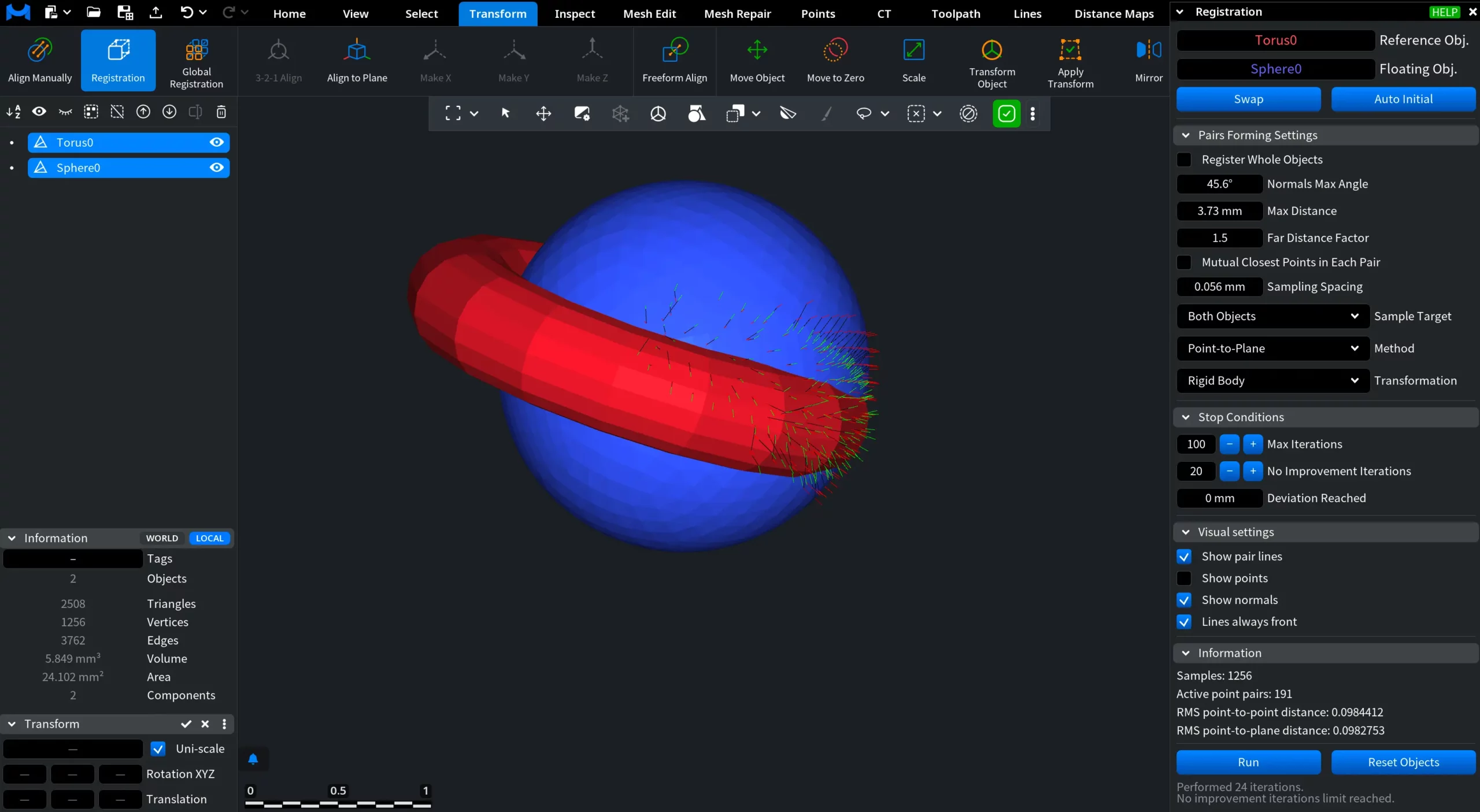
Clicking Registration, located under the Transform tab, allows you to calculate a transformation that aligns a floating object with a reference object by minimizing geometric differences between them.

The process uses the Iterative Closest Point (ICP) algorithm, which progressively refines the alignment by establishing and updating point correspondences between the two objects. The tool is intended for automatic fine alignment.
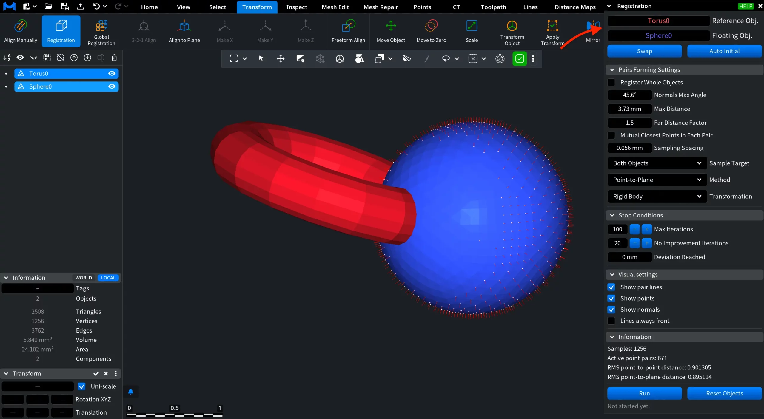
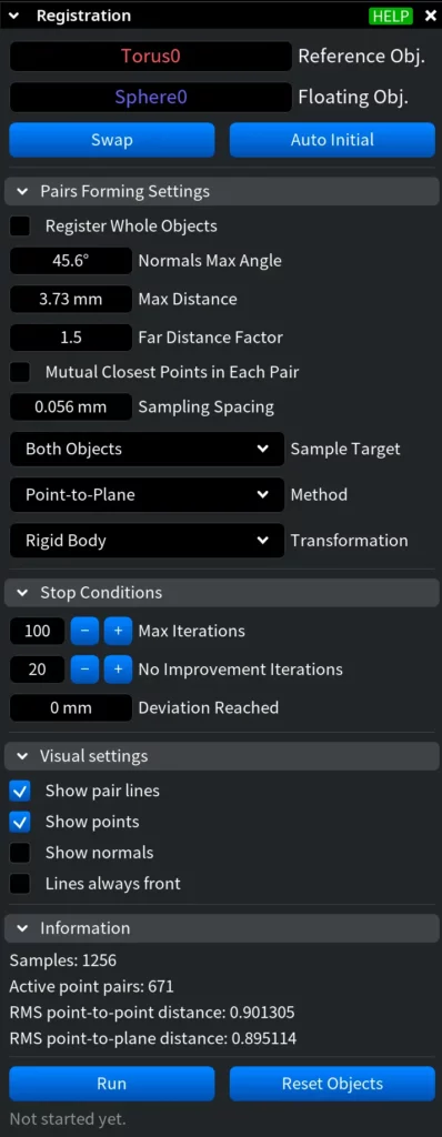
When the tool is activated, a settings panel opens. At the top of the panel, you can define the participating objects:
- Reference Object is the fixed object that remains stationary during registration.
- Floating Object is the object that is transformed to align with the reference.
Below, two action buttons are available:
- Swap exchanges the roles of the reference and floating objects.
- Auto Initial automatically calculates an initial transformation for the floating object. This provides a suitable starting position and can improve ICP convergence, especially when the objects are initially far apart.
Pairs Forming Settings
The Pairs Forming Settings section controls how point pairs are formed and filtered during registration.
- Register Whole Objects, when selected, considers all point pairs between the two objects during registration without filtering.
- Normals Max Angle defines the maximum permitted angle between the normals at two points. A point pair is used only if the angle does not exceed this value.
- Max Distance defines the maximum permitted distance between two points. A point pair is used only if the distance is lower than this value.
- Far Distance Factor defines an additional distance threshold based on the root-mean-square distance. A point pair is counted only if the distance between its points is lower than the root-mean-square distance multiplied by this factor.
- Mutual Closest Points in Each Pair, when selected, forms a point pair only if the two points are mutually closest to each other. In other words, the pair must pass the reciprocity test.
- Sampling Spacing defines the sampling voxel size. Only one point is selected from each voxel.
- Sample Target determines which objects are sampled to form the origins of point pairs. The available options are:
- Both Objects
- Floating Only
- Reference Only
- Method specifies the target function to minimize. The available options are:
- Combined
- Point-to-Point
- Point-to-Plane
- Transformation specifies the types of transformation to search for. The available options are:
- Rigid + Scale
- Rigid Body
- Orthogonal Axis Rotation
- Fixed Axis Rotation
- Translation Only
Stop Conditions
The Stop Conditions section defines when the ICP algorithm stops iterating.
- Max Iterations specifies the maximum permitted number of ICP iterations.
- No Improvement Iterations stops ICP if no improvement has been achieved during the specified number of most recent iterations.
- Deviation Reached defines the target root-mean-square distance. Once this value is reached, the algorithm stops.
Visual Settings
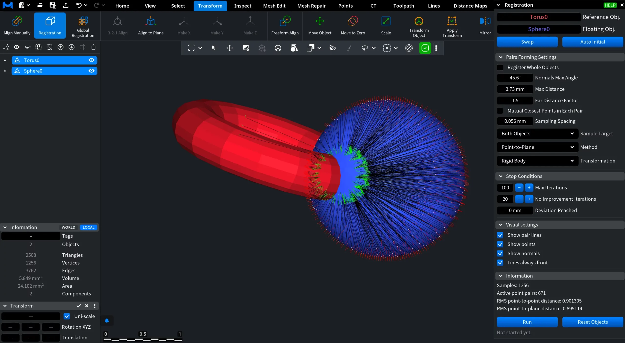
The Visual Settings section controls which auxiliary registration elements are displayed in the viewport.
- Show pair lines, when selected, displays lines connecting the paired points.
- Show points, when selected, displays the points used to form the pairs.
- Show normals, when selected, displays the normals at the points.
- Lines always front, when selected, displays the pair lines in front of the objects so that they remain visible even when they would otherwise be obscured by the object surfaces.