In many 3D workflows, precise object placement is critical. Even when it comes to minor misalignments, these can bring about errors during inspection, measurement, manufacturing preparation, further geometric processing, etc. To avoid these issues, your models are to be aligned in a predictable and repeatable way.
The MeshInspector program provides several tools for object alignment. Previously, we covered Align to Plane. It allows one to orient a model relative to a single reference plane. While fast and convenient, aligning an object to just one plane frequently does not suffice.
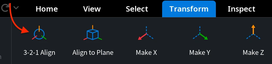
To address this, the MeshInspector team offers the 3-2-1 Align tool, located under the Transform tab, like Align to Plane. This tool is designed for full, deterministic alignment, allowing you to define both the orientation and the position of a model across all three global axes.
How the 3-2-1 Align Workflow Looks
The 3-2-1 Align workflow is based on a simple, step-by-step principle:
- At least three points (or more) define a reference Plane;
- Two points minimum (or more) define a direction Vector;
- One point defines the final Point position.
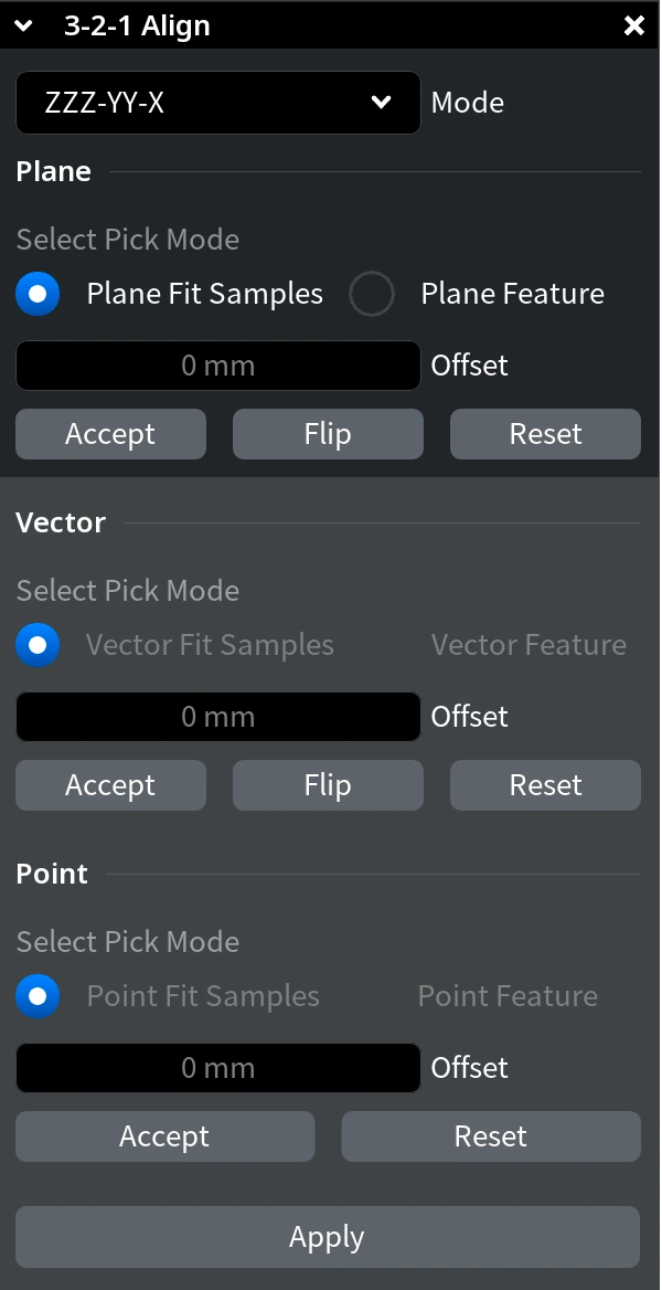
Once you activate 3-2-1 Align under the Transform tab, you will see a dedicated tab, showing the sequence of actions to execute. Together, these three steps will fully determine how the model is oriented and positioned in 3D space.
You can define these references in two ways:
- By selecting points directly on the geometry using Fit Samples;
- By using pre-created features, i.e., planes, lines, and points created in advance, using feature-based references (Plane, Vector, and Point features).
In this guide, we start with the default alignment mode and the Fit Samples approach.
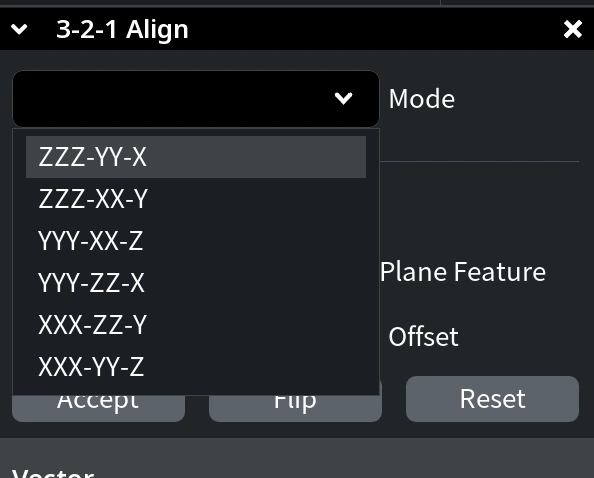
Note: The Mode dropdown defines the alignment sequence and the target global axes for each step. By changing the mode, you are free to control which axes are used for plane alignment, vector direction, and final positioning. For simplicity, this tutorial focuses on the default mode: ZZZ-YY-X.
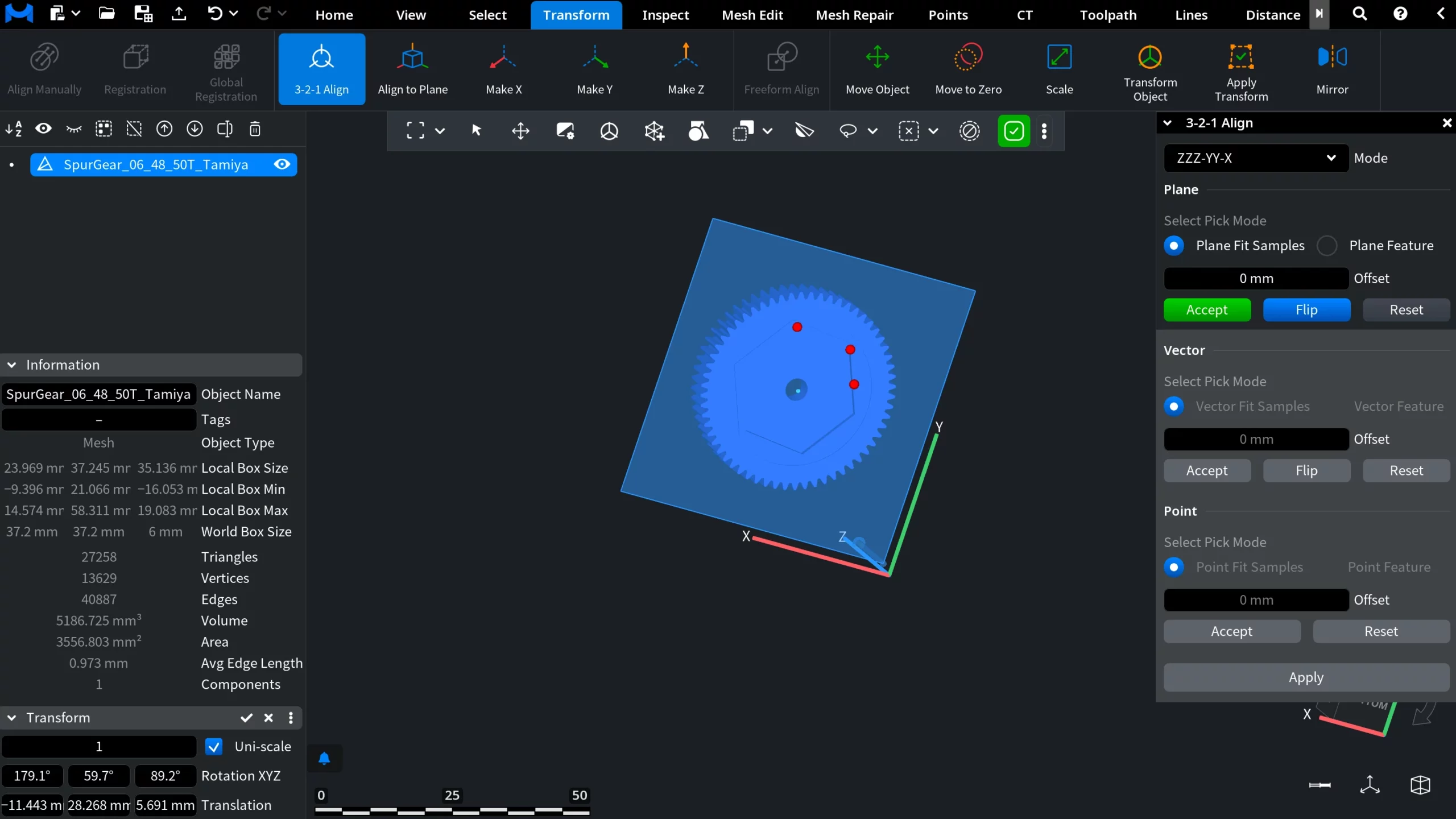
Step 1: Defining the Reference Plane With the Pick Mode
Click directly on the model to place and drag points that define the reference plane. A minimum of three points is a must. You may place additional points if needed and adjust their positions, but at least three are mandatory.
Once the plane is defined using the selected points, click Accept to confirm this step.
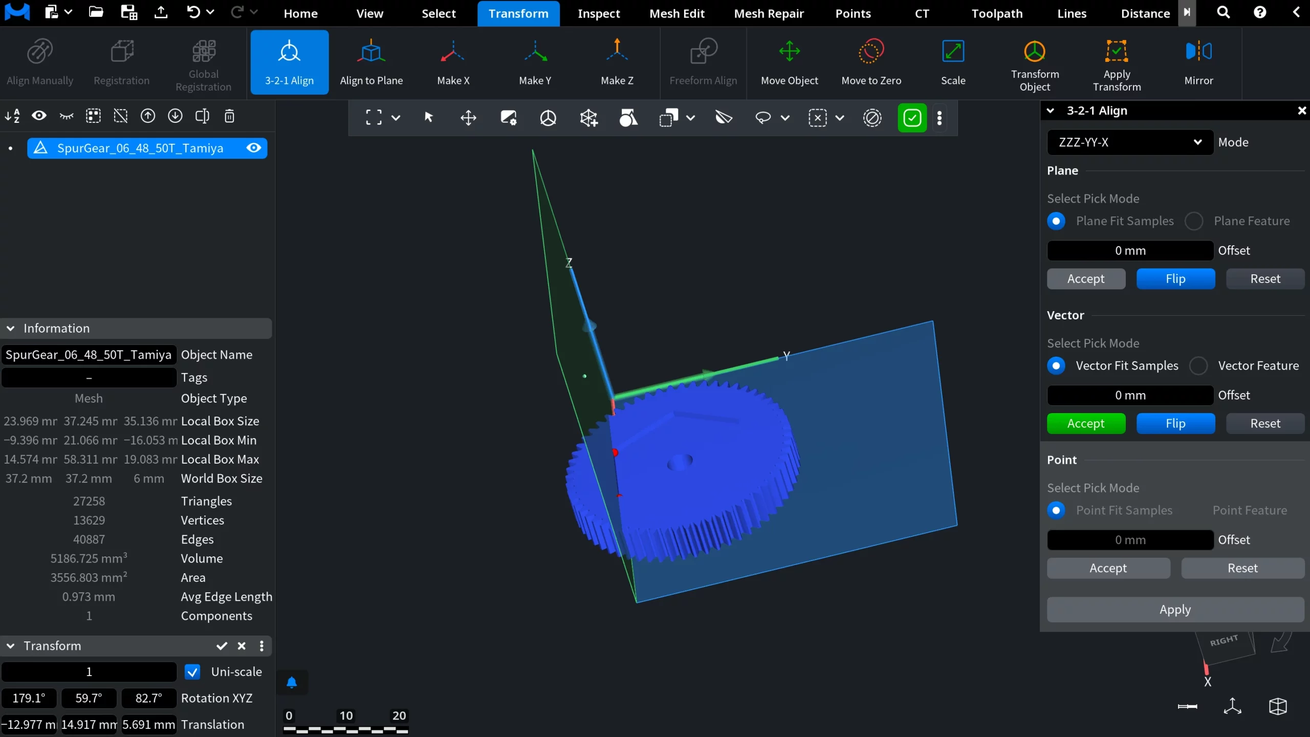
Step 2: Defining the Direction Vector
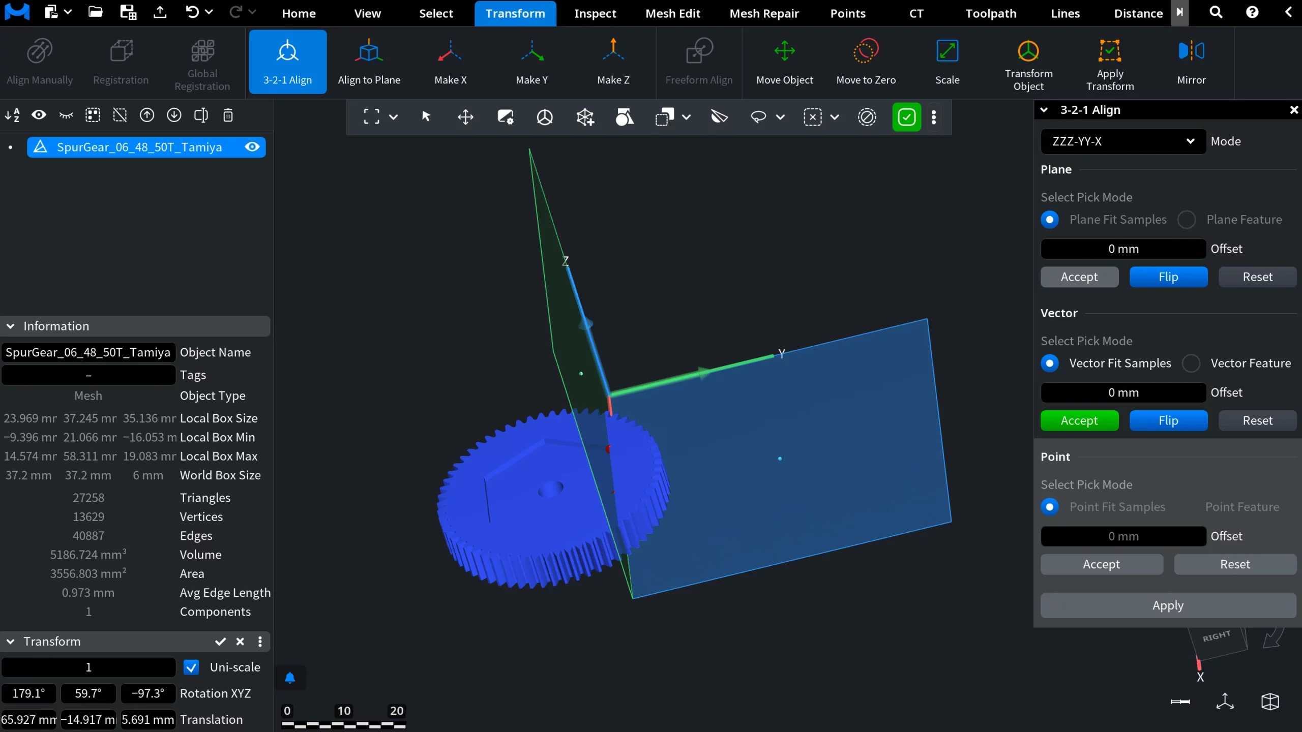
Next, move on to the Vector step. Here, select at least two points to define a direction vector. This vector controls how the model is rotated within the previously defined plane and determines which direction should be aligned with the selected global axis. If the vector points in the wrong direction, use the Flip option to reverse it without changing the selected points.
Before flipping
After flipping
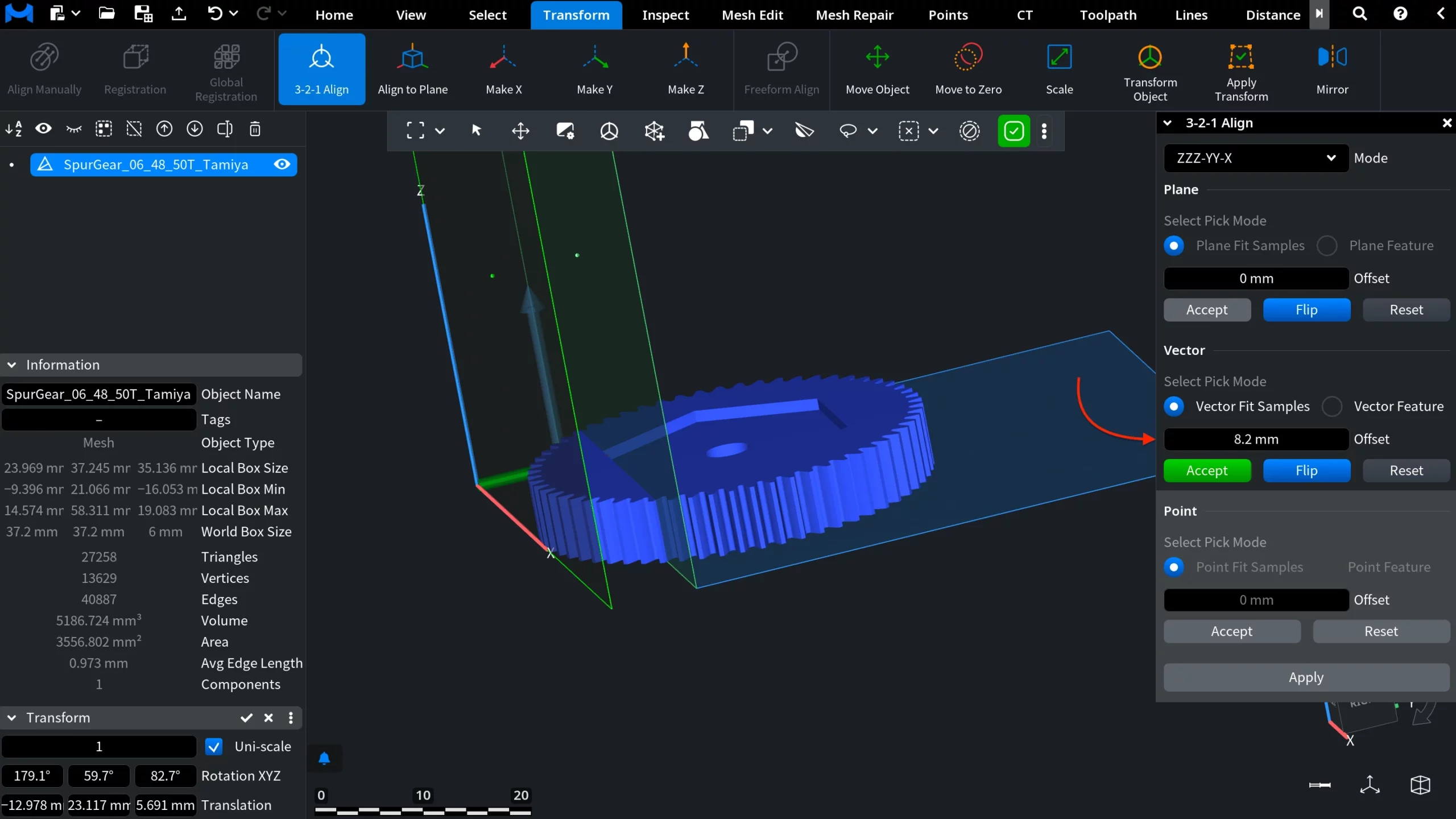
Using Offset
Further, the Offset option allows you to shift the alignment reference by a defined distance. This is useful when the alignment reference should not lie directly on the selected geometry.
The offset value can be adjusted in two ways:
- Entering a value manually for precise control
- Dragging the offset interactively for visual adjustment
Once the vector and offset are set, click Accept to proceed.
Step 3: Defining the Final Position
In the final Point step, select one point to define the model’s position relative to the global coordinate system. After selecting the point, click Accept, then click Apply to complete the alignment process. At this stage, the model is fully aligned and positioned across all three axes.

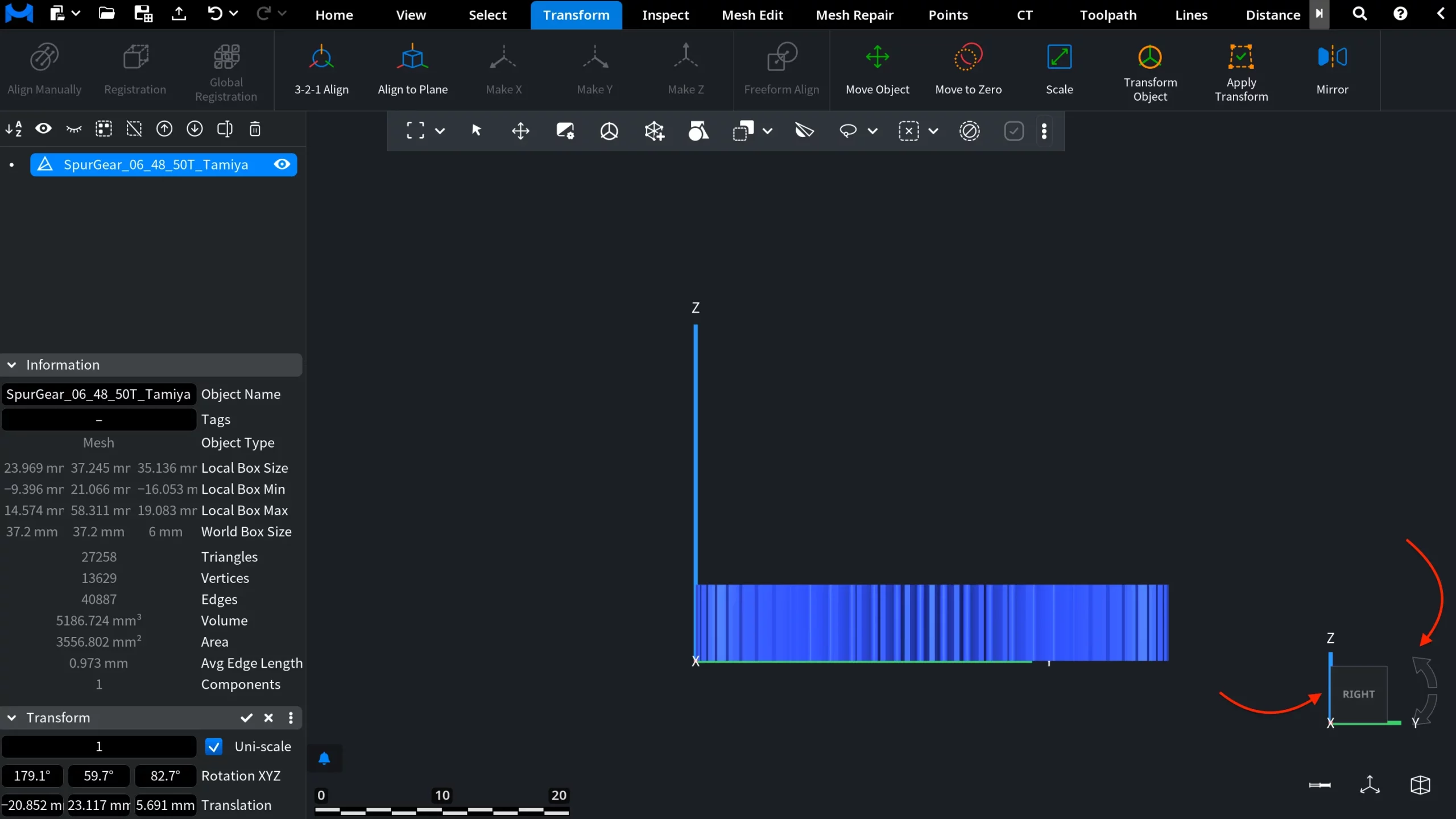
Step 4: Verifying the Alignment
To verify the result, use the navigation cube and arrows to inspect the object from different angles. This allows one to confirm that the object is properly aligned with the global coordinate system.
Aligning Using Pre-Created Features
Apart from selecting points directly on geometry, MeshInspector's 3-2-1 Align functionality is fully equipped to work with pre-created features. To try this approach, switch to the Inspect tab and create a Plane, followed by a Line, and finally a Point.
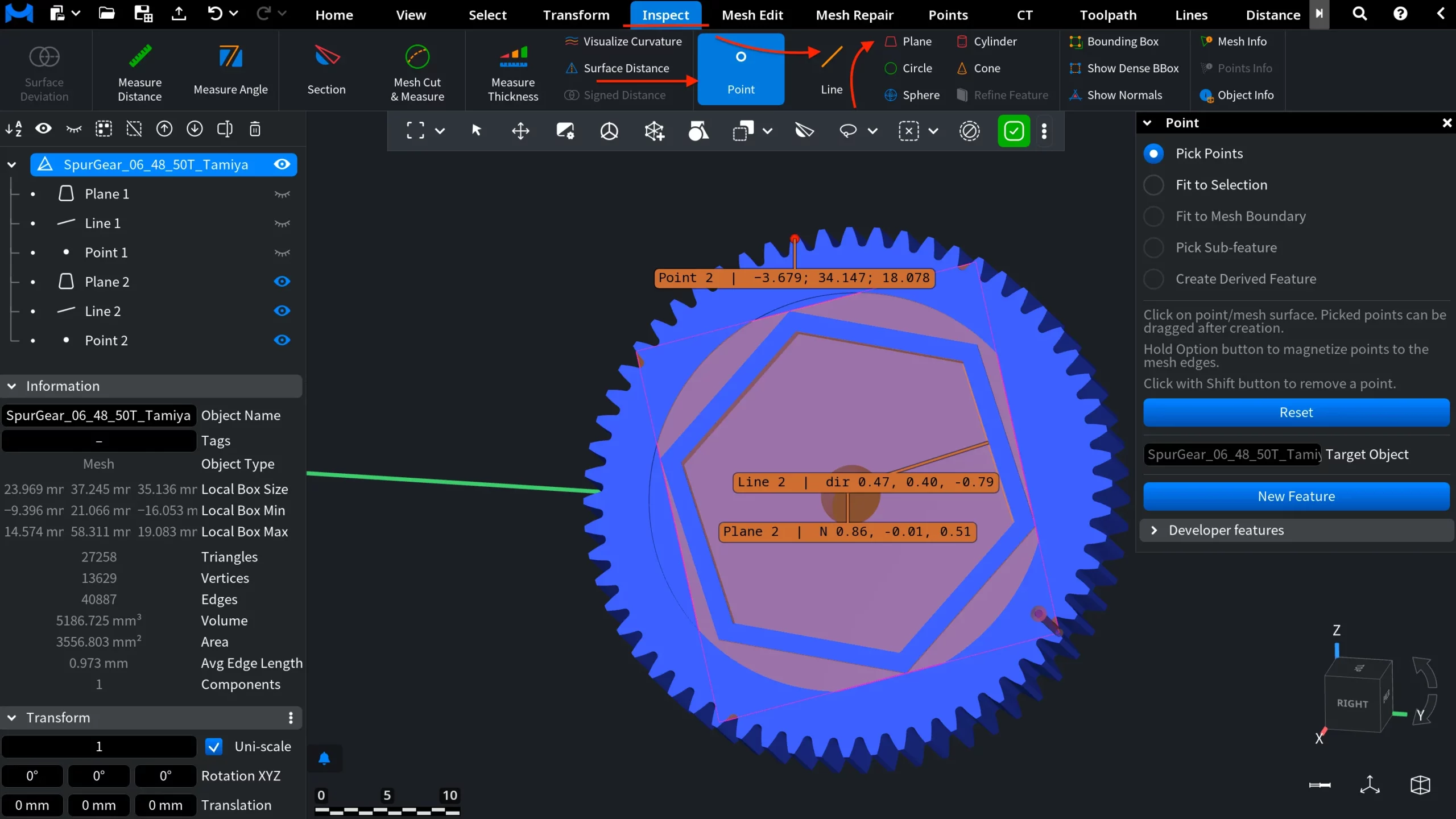
Once all three features are created, return to the Transform tab, open 3-2-1 Align, and switch to the Feature option.
Select the plane, line, and point features sequentially. Each step must be confirmed by clicking Accept. Make sure to click directly on the feature itself, not on its name.
After accepting all three features, click Apply. You can then hide the reference features and evaluate how accurately the object is positioned.
When to Use 3-2-1 Align
MeshInspector's 3-2-1 Align tool at your disposal is especially useful when alignment is to be:
- First, precise;
- Second, explainable;
- Third, sufficiently consistent for inspection, manufacturing, and downstream workflows.
By combining planes, vectors, and points into a structured alignment process, MeshInspector makes it easier to prepare models correctly when accuracy matters.
Wrapping 3-2-1 Align Workflows Up
The 3-2-1 Align tool provides full control over how a model is oriented and positioned in 3D space. Whether you work directly with raw geometry or with explicitly defined features, this workflow ensures predictable alignment results and reduces the risk of downstream errors.