In MeshInspector, the Surface Deviation tool visualizes geometric differences between two objects by computing and displaying the distance between their surfaces. The result is shown as a color-coded deviation map applied to the inspected object, making it easy to identify areas where geometry differs from a reference. The tool itself is located under the Inspect tab.

Note: the Surface Deviation tool requires exactly two visual objects that can be compared geometrically.
Surface Deviation becomes available only in one of these valid cases:
-
Exactly two meshes.
-
Exactly two point clouds.
-
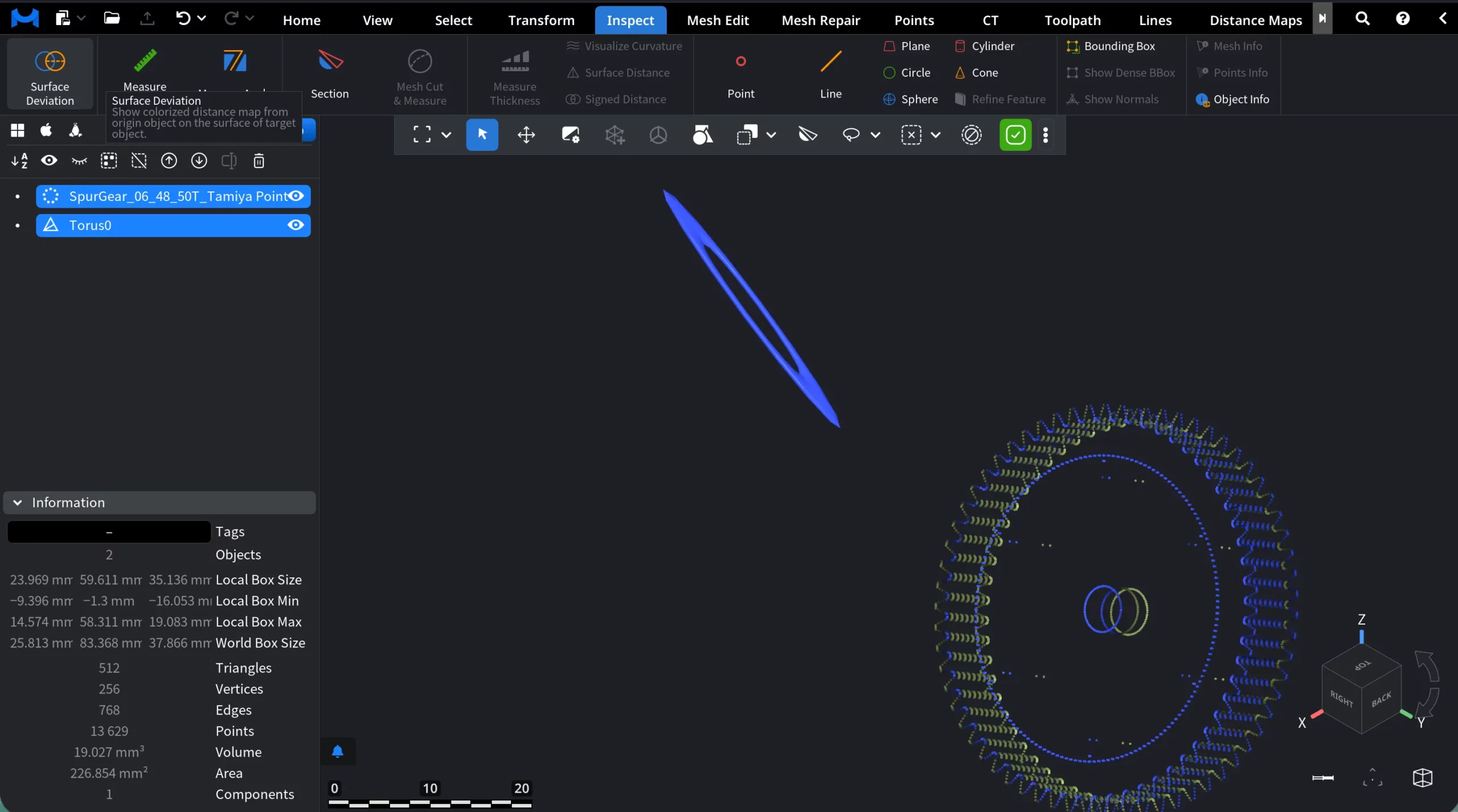
Two Visual Objects, where one is a Mesh and the other is a Point Cloud, like it is shown in the screenshot below.
Two objects before clicking Surface Deviation
When Surface Deviation is activated (with a valid selection), MeshInspector switches the viewport into deviation inspection mode. New elements appear.
Two objects after clicking Surface Deviation
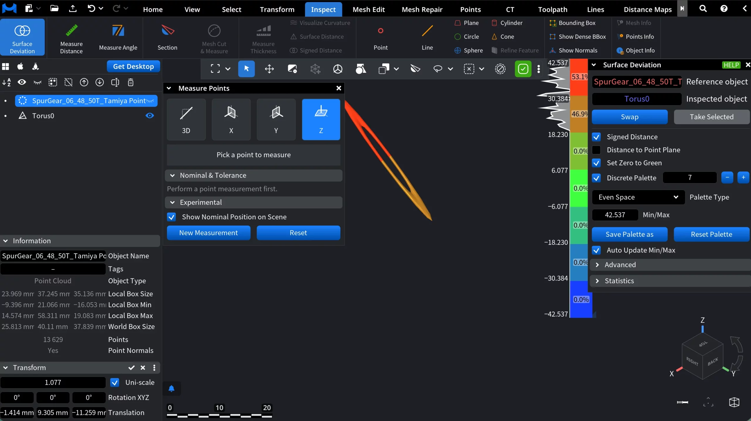
1. Deviation color map on the inspected object
The inspected object is overlaid with a false-color deviation map.
- Colors represent the signed distance between the inspected object and the reference object.
- Green corresponds to zero deviation.
- Warm colors indicate positive deviation.
- Cool colors indicate negative deviation.
This color overlay is applied directly to the object’s surface.
2. Deviation legend (vertical color ruler)
A vertical color scale appears in the viewport. This is the “ruler” you are seeing in the screenshot. It shows:
- The full deviation range (Min / Max) in model units.
- Discrete or continuous color bands.
- Percentage distribution per band.
The legend provides immediate quantitative context for the colorized result.
3. Surface deviation panel
When Surface Deviation is activated, a dedicated Surface Deviation panel opens on the right side of the interface. This panel controls how deviation is computed, visualized, and interpreted.
4. Measure points panel
A floating Measure Points panel becomes available in the viewport. This panel allows you to pick specific points and measure distance between them. This tool complements the color map by enabling precise and point-level inspection.
Surface Deviation Panel: Settings and Actions
The Surface Deviation panel controls how distances between the reference and inspected objects are computed, visualized, and interpreted.
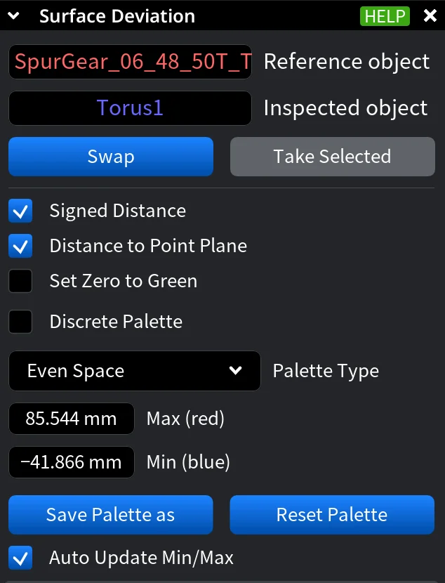
Reference and Inspected objects
- Reference object is the object used as the baseline for distance calculation. Distances are measured from this object.
- Inspected object is the object that receives the color-coded deviation map.
- Swap exchanges the reference and inspected objects.
- Take Selected replaces the current reference and inspected objects with the two objects that are currently selected in the scene.
Signed Distance. When enabled, deviation values are signed:
- Positive values indicate the inspected object lies outside the reference object.
- Negative values indicate the inspected object lies inside the reference object.
If disabled, all distances are treated as absolute (unsigned).
Distance to Point Plane. When enabled, distance is computed to a plane defined by the nearest point on the reference object and its normal, rather than directly to the closest surface point. This can produce less intuitive color patterns.
Set Zero to Green forces zero deviation to always be displayed as green, regardless of palette configuration.
Discrete Palette. When enabled, the continuous deviation range is split into a fixed number of discrete color bands.
- The numeric field defines the number of discrete levels.
- The + and - buttons increase or decrease the number of bands.
When disabled, the palette is continuous.
Palette Type defines how the deviation range is distributed across colors. Even Space means the full Min/Max range is divided evenly. Each color band represents the same numerical distance interval. As for Central Zone, it emphasizes a tolerance zone around zero deviation. As such, it allows you to define:
- Max positive (red)
- Min positive (green)
- Max negative (green)
- Min negative (blue)
The active palette type determines which numeric fields are displayed below.
Min / Max with Even Space defines the numerical limits of the color scale:
- Max (red) is highest positive deviation
- Min (blue) is lowest negative deviation
In Central Zone mode, these are split into four separate bounds.
- Save Palette as saves the current palette configuration for reuse.
- Reset Palette restores the default palette and range settings.
- Auto Update Min/Max, when enabled, adjusts the palette automatically whenever the deviation data changes.
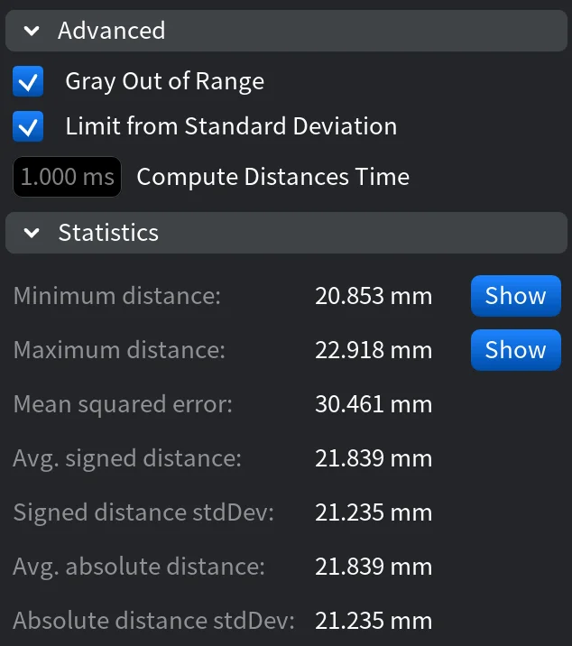
Advanced Settings
Gray Out of Range renders deviation values outside the current palette range in gray. This helps visually suppress outliers and can improve performance, especially when signed distance is enabled.
Limit from Standard Deviation controls how automatic Min/Max limits are calculated when Auto Update Min/Max is on:
- Enabled: limits are set to signed mean ± 3× standard deviation.
- Disabled: limits are taken directly from the absolute Min/Max values.
This option is available only when Set Zero to Green is disabled.
Compute Distances Time displays the time spent on the last deviation computation (in milliseconds). This is a read-only performance indicator.
Statistics
The Statistics section provides numerical summaries of the computed surface deviation between the reference and inspected objects.
Measure Points Panel
Measure Points is a precision tool that lets you inspect exact distances between two picked points on the inspected object, complementing the surface color map with numeric measurements. After activating Surface Deviation, the Measure Points panel appears as a floating window in the viewport.
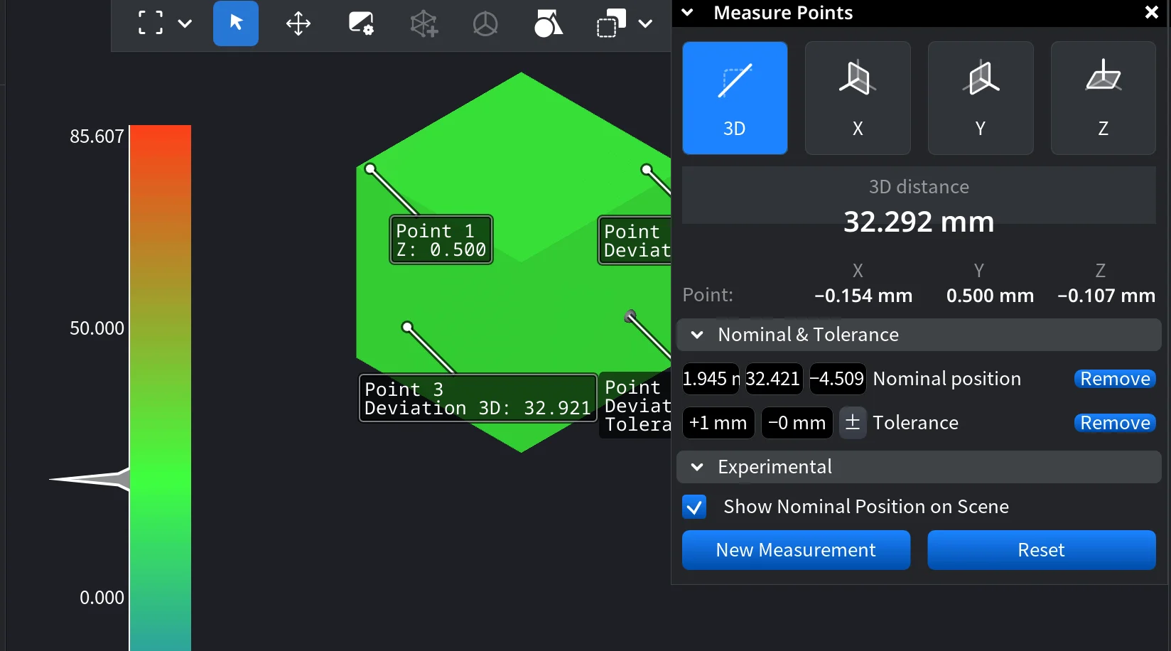
Measurement Modes
- 3D measures the true 3D distance between two points.
- X / Y / Z measure the distance projected onto the selected axis only.
Measurement Readout
- The main value shows the measured distance in model units.
- In 3D mode, individual X, Y, and Z components are also displayed.
- Labels in the viewport indicate each picked point and its deviation value.
Nominal Position and Tolerance
This section allows you to define a nominal position and an acceptable tolerance range for the measurement.
- Nominal position stores a reference value for comparison.
- Tolerance (±) defines allowable deviation from the nominal value.
- When enabled, tolerance feedback is shown directly in the scene.
Experimental
-
Show Nominal Position on Scene displays the nominal reference visually in the viewport for easier comparison.
Actions
- New Measurement starts a fresh point-picking sequence.
- Reset clears the current measurement and removes markers.