
Loads from YouTube (Google) when you press Play
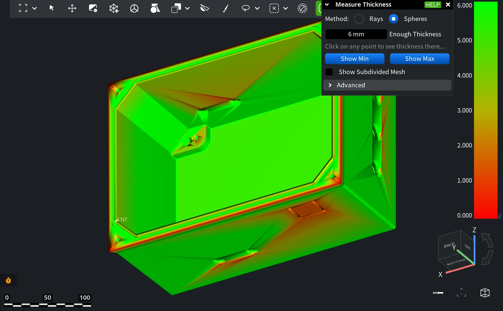
Measure Thickness colors a mesh by its local wall thickness, so you can see at a glance where the walls are too thin, for example before you 3D print a housing. Select one mesh and click Inspect › Measure Thickness. The calculation starts at once; the colors appear on the model and a color scale appears on the right of the viewport. The mesh itself is not changed, and the colors disappear when you close the tool.
Prepare the Model
- Select one mesh. The tool works on meshes, not on point clouds.
- For the Rays method, the normals must point outward: rays go into the material, opposite to the normal. Check the mesh with Show Normals and fix it with Orient Mesh Normals if needed.
- Where a ray finds no opposite side, for example because it leaves the mesh through a hole, no thickness is measured. Close holes first with Fill Holes.
How Thickness Is Computed
The tool computes a thickness value at every vertex of the mesh. Method sets how.
Spheres Method
Spheres is the default. The thickness at a point is the diameter of the largest sphere that fits inside the mesh and touches the surface at this point. When you click a point, the line goes from the point through the center of this sphere to where it touches the other side. For noisy surfaces and special cases, see Advanced Settings.
Rays Method
With Rays, the thickness at a point is the distance from the point straight into the material, opposite to the surface normal, to the other side of the mesh. When you click a point, the line shows this ray.
Find Walls Thinner Than a Limit
- Select the mesh and click Inspect › Measure Thickness.
- Keep the Spheres method or switch to Rays.
- In Enough Thickness, enter your limit in scene units, for example
0.8if your print process needs walls of at least 0.8 mm. By default, the field is set halfway between the smallest and the largest thickness found on the model, and it accepts only values in this range: if your limit is below the smallest thickness, no wall is thinner than the limit. - Read the colors: green is the limit or thicker, yellow to red is thinner, red is the thinnest.
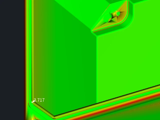
- Click Show Min to mark the thinnest point, or click any point of the model: a line across the wall and a label with the thickness appear there. On CAD parts with sharp edges, the smallest value found with Spheres can be close to zero (on the housing in the picture, the range started at almost 0), so look at what Show Min marks before you trust it.
To make thin walls thicker, use Hollow / Thicken or Offset. To measure a wall by hand on a cut, use Section.
Panel Settings
| Setting | What it does |
|---|---|
| Method | Rays or Spheres, see above. Changing it recomputes the colors. |
| Enough Thickness | Places with this or larger thickness are green, thinner places are yellow and red. |
| Show Min / Show Max | Marks the point with the smallest or the largest thickness and shows its value. |
| Show Subdivided Mesh | Shows the thickness on a subdivided copy of the mesh for a smoother color map. The mesh itself is not changed. |
Advanced Settings for Spheres
The Advanced section appears when Method is Spheres:
| Setting | What it does | Default |
|---|---|---|
| Signed Curvature | Shows surface curvature instead of thickness: the inverse radius of the largest sphere that touches the surface at each point. Enough Thickness turns into Maximum Curvature: zero curvature is green, large positive curvature is blue, large negative curvature is red. | Off |
| Max Angle | The largest allowed angle between the search direction and the direction from the sphere's center to the other touch point. Lower it on noisy surfaces to avoid too small spheres. | 90° |
| Maximum Sphere Radius | The largest allowed sphere. It is set automatically from the model size; change it only if the automatic value fails. | Automatic |
| Recalculate | Computes the colors again with the new settings. |


