Loads from YouTube (Google) when you press Play
This article explains how MeshInspector’s Offset tool works. Mesh offsetting involves creating a parallel surface at a specified distance from the original mesh. This operation is crucial in industries such as 3D printing and injection molding, where precise control over surface thickness is required.
To start using the tool, go to the Mesh Edit tab and, with the object selected, click Offset.

The dedicated Offset panel will then open. Its appearance and available options depend on whether any regions of the object are selected.
When No Regions Are Selected
If there are no selected regions, five offset modes are available.
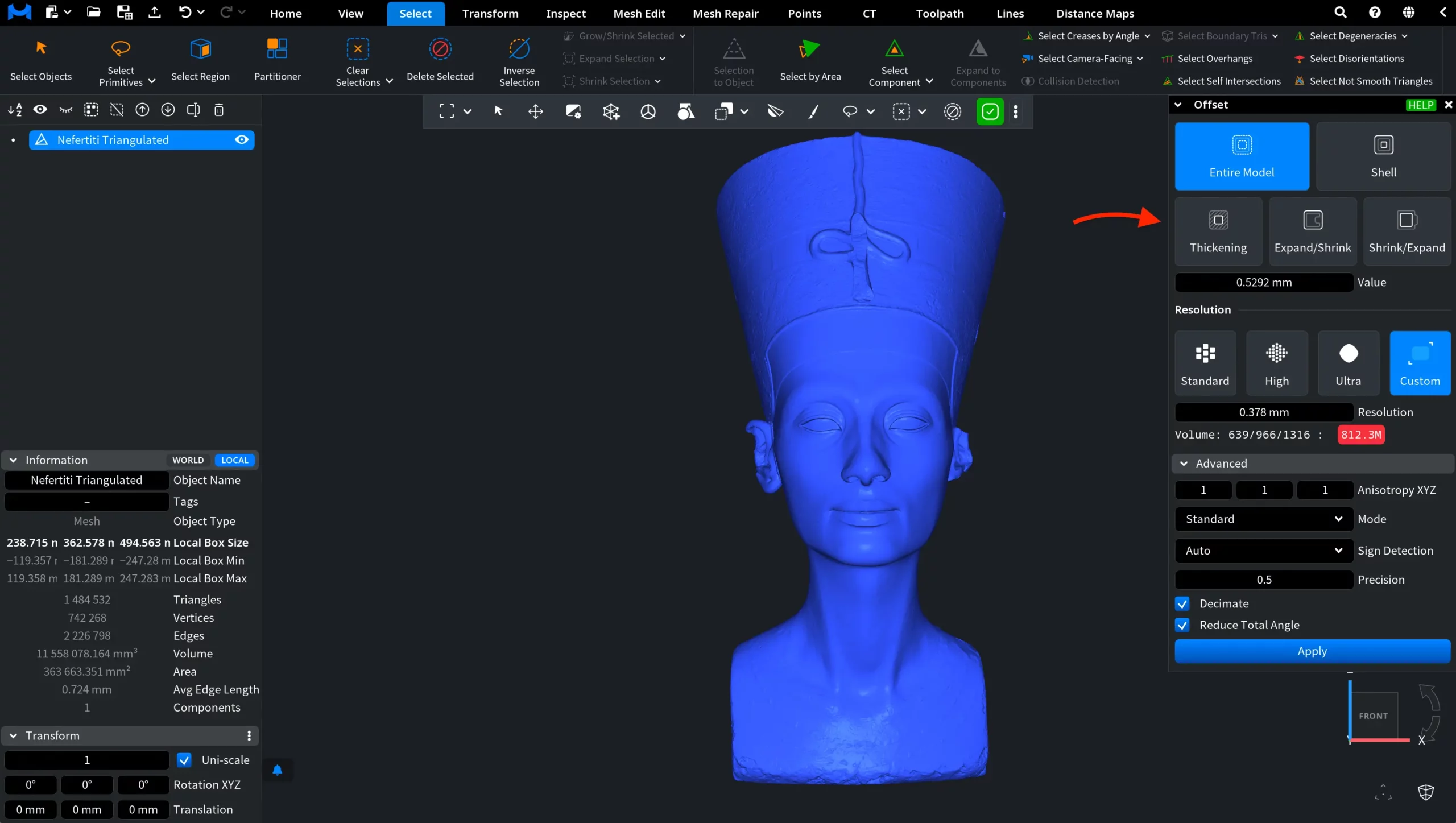
1. Entire Model Offset Mode
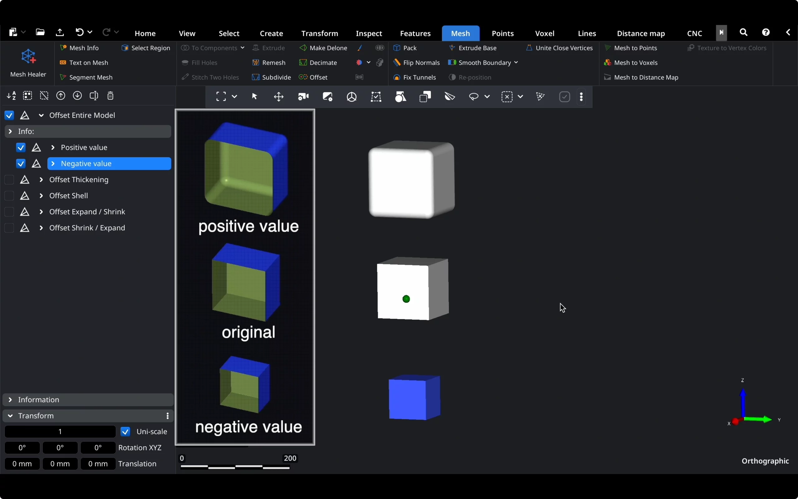
-
Purpose: Uniformly offsets the entire mesh.
-
How It Works: A positive value pushes the mesh outward by the specified distance in millimeters, while a negative value pulls it inward.
2. Thickening Mode
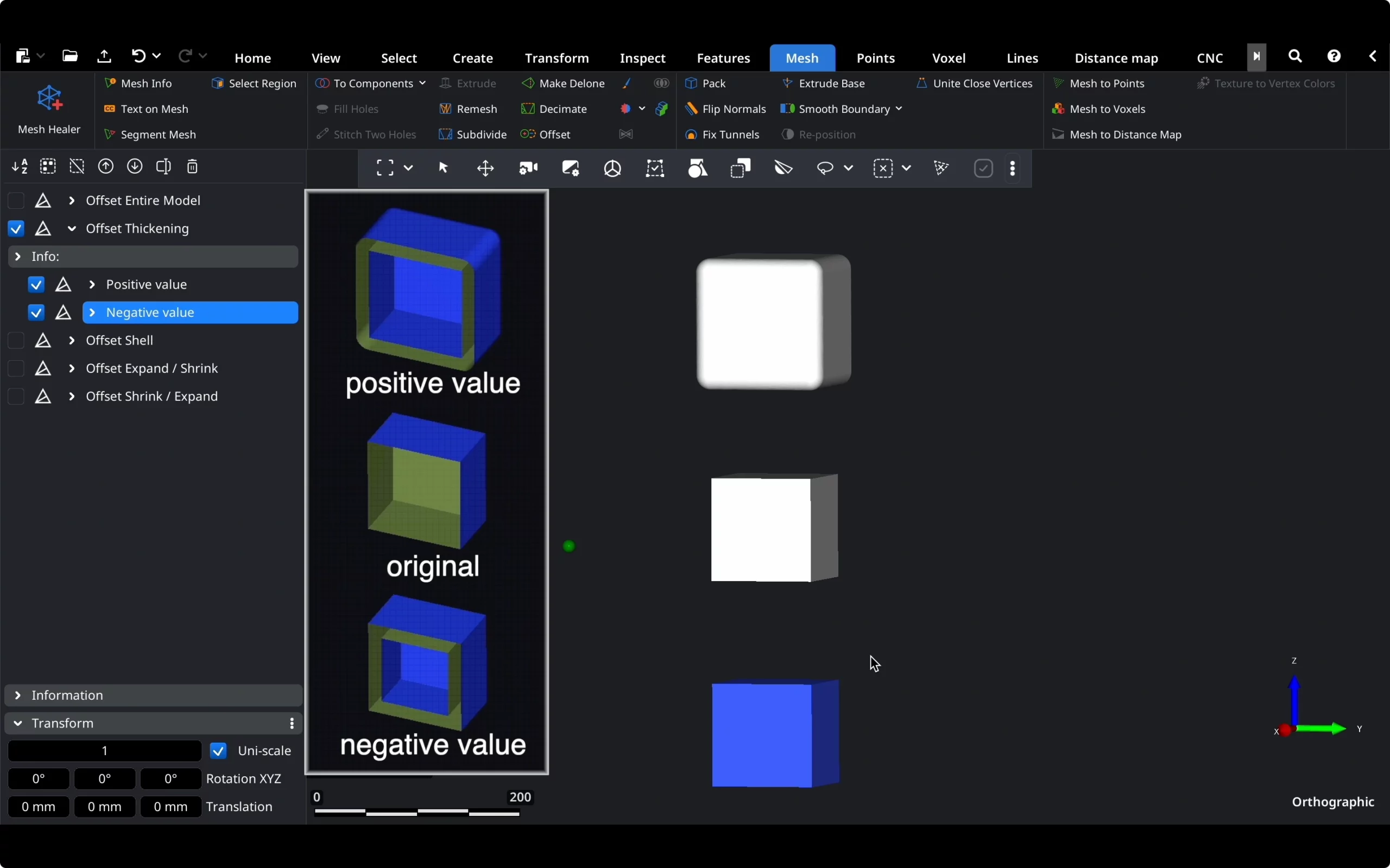
-
Purpose: Creates an additional surface, effectively thickening your model.
-
How It Works: A positive value creates an additional layer outside the original model, while a negative value creates it inside.
3. Shell Mode
-
Purpose: Creates two new surfaces in both directions and eliminates the original mesh.
-
Use Case: Useful for creating a hollow part for mold making.
4. Expand/Shrink Mode
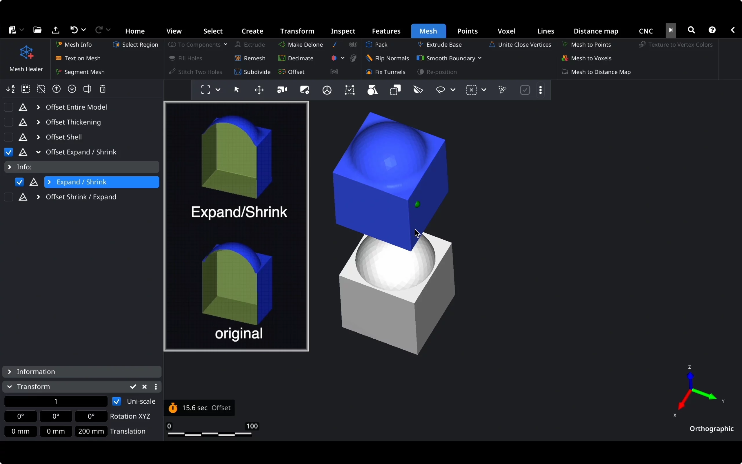
-
Purpose: Smooths concave features and increases the model volume.
-
How It Works: Expands the mesh by a set distance and then shrinks it, resulting in a smoothed surface.
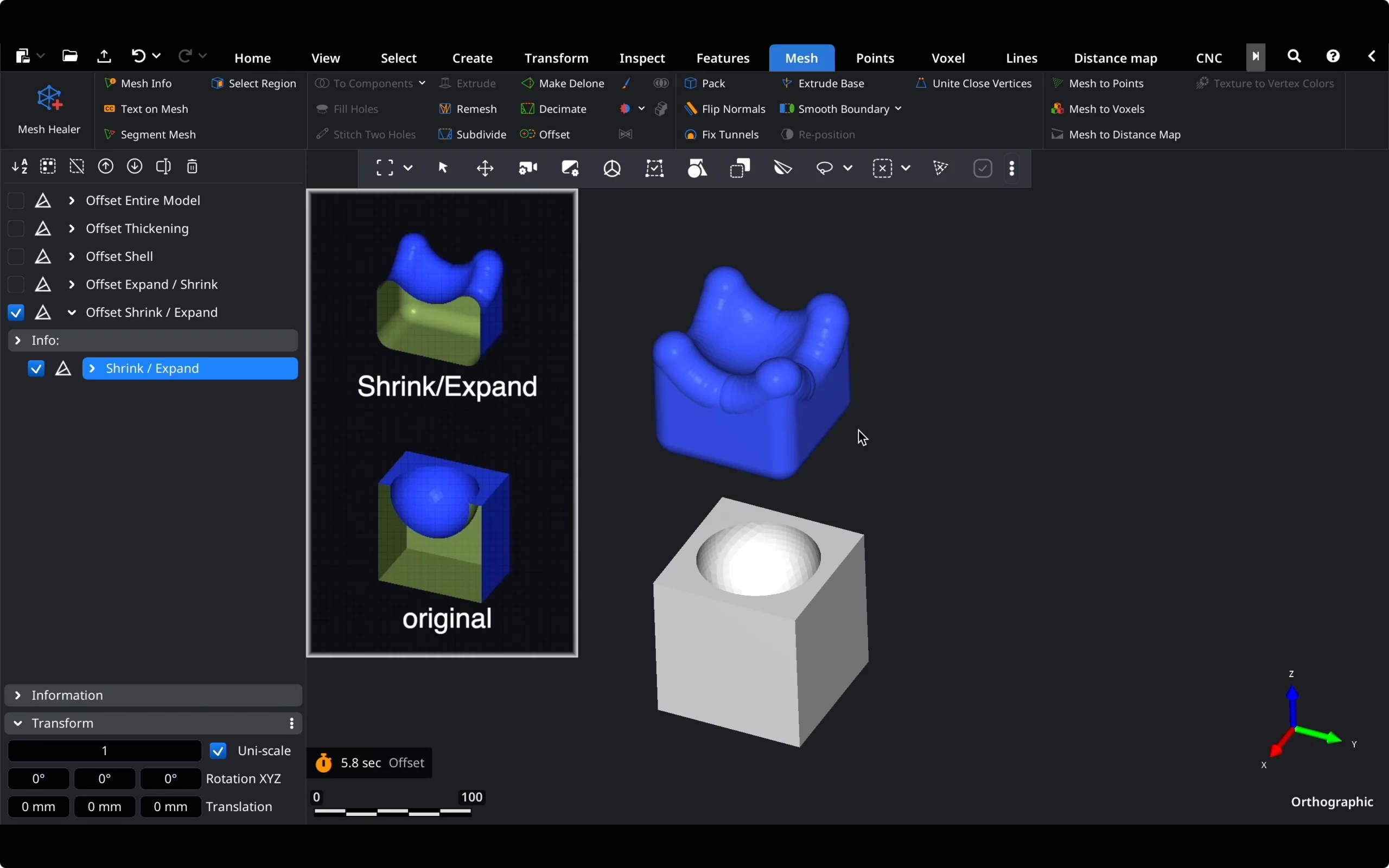
5. Shrink/Expand Mode
-
Purpose: Smooths convex features and decreases the model volume.
-
How It Works: Shrinks the mesh by a set distance and then expands it, smoothing out noise or minor imperfections on complex surfaces.
Below the five modes, the Value field allows you to specify the offset distance from the original surface.
Resolution
The Resolution section controls the voxel size used to calculate the offset. A finer resolution preserves more geometric detail but requires more processing time and memory.
1. Standard provides a balance between output quality and processing speed. This preset is suitable for most routine offset operations.
2. High uses a finer resolution to preserve more surface detail. Processing may take longer than with the Standard preset.
3. Ultra uses the finest preset resolution for maximum detail. This option may require significantly more processing time and memory.
4. Custom allows you to specify the voxel size manually in the Resolution field. A smaller value produces a more detailed result but increases the number of voxels and the computational resources required.
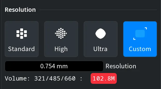
When Custom is selected, the panel also displays the dimensions of the voxel volume along the three axes and the total number of voxels. This information helps you estimate how resource-intensive the operation will be.
Advanced Settings
In the Advanced section, you can configure six settings that control how the offset is calculated and how the voxel data is converted into the resulting mesh.
Anisotropy XYZ allows you to increase the offset along a particular axis. The three fields correspond to the X, Y, and Z directions. A value greater than 1 increases the offset along that axis proportionally. At least one of the three values must remain set to 1.
Mode determines how the generated voxel data is converted into the final mesh. Three options are available:
- Smooth uses the Dual Marching Cubes algorithm, producing smoother surfaces and more rounded corners.
- Standard uses the standard Marching Cubes algorithm, preserving corners more sharply than Smooth mode.
- Sharpening uses the standard Marching Cubes algorithm together with additional post-processing intended to emphasize sharp features in the resulting mesh.
Sign Detection determines how the tool distinguishes the interior of the mesh from its exterior when calculating the signed distance for each voxel.
- Auto automatically selects the fastest suitable method from the safe options available for the current mesh.
- Winding Number uses a generalized winding-number method. It supports meshes containing holes and self-intersections.
- Projection Normal determines the sign using the pseudonormal at the closest point on the mesh. This method is fast but may produce unreliable results when the mesh contains holes or self-intersections.
Precision controls the precision parameter used during the offset calculation.
Decimate, when enabled, performs mesh decimation after reconstruction. This removes short edges and degenerate triangles and can reduce unnecessary geometric complexity in the resulting mesh.
Reduce Total Angle optimizes the resulting triangulation by minimizing the total deviation of angles between adjacent triangles from a common plane. This can help preserve and emphasize sharp edges. When Decimate is enabled, this optimization is applied both before and after decimation, which may further reduce the number of triangles in the final mesh.
When Regions Are Selected
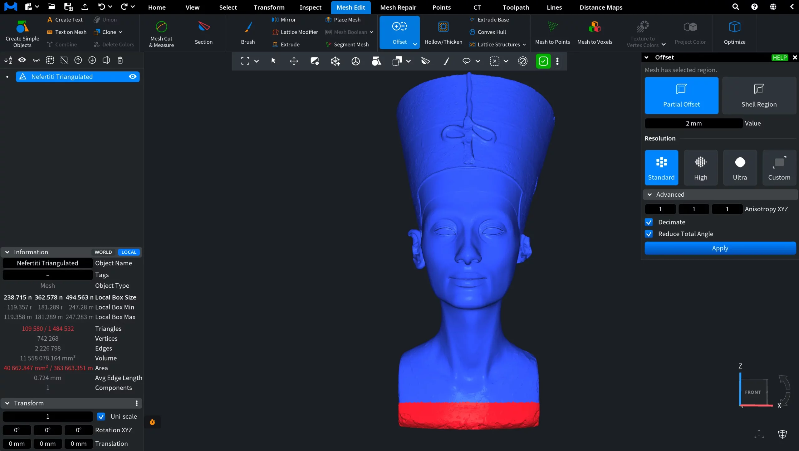
When one or more regions are selected on the mesh, the Offset panel switches to a region-based workflow and provides two modes: Partial Offset and Shell Region.
1. Partial Offset
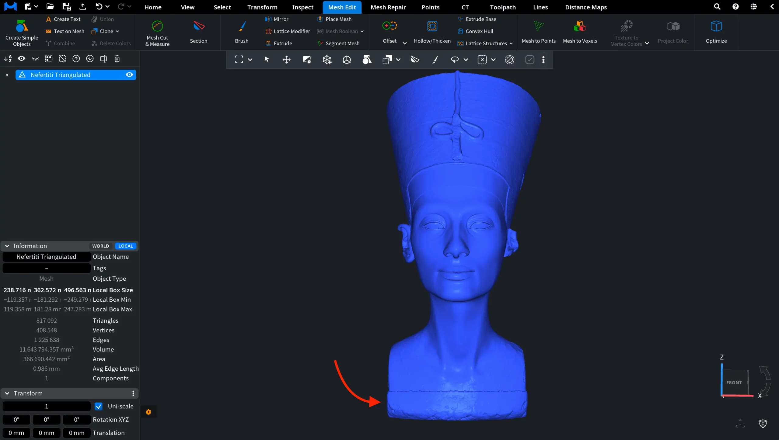
Partial Offset moves the selected region by the distance specified in the Value field while leaving the rest of the mesh in its original position. An example of Partial Offset applied to the bust base is shown below.
2. Shell Region
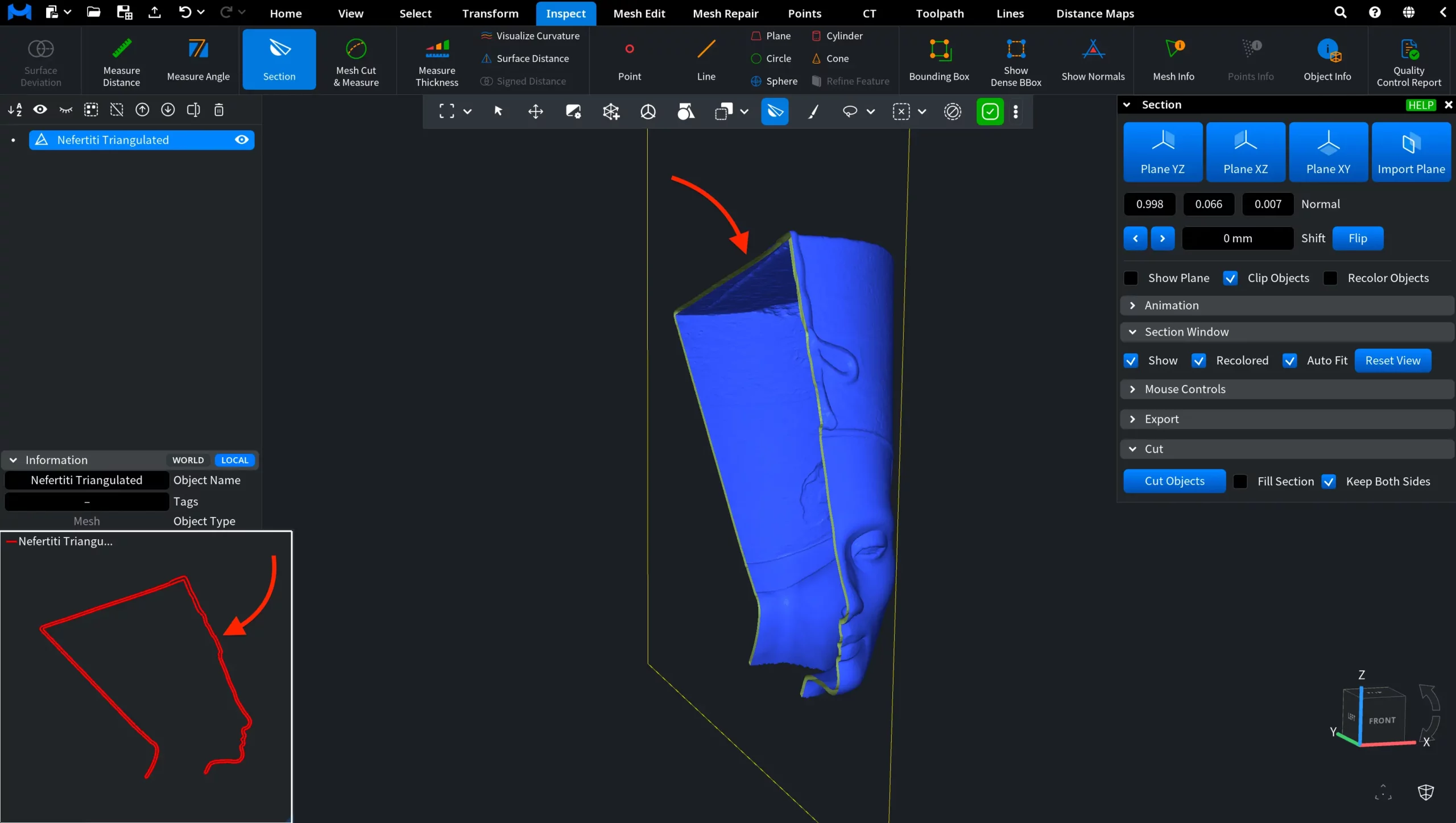
Shell Region constructs a shell around the selected mesh region. The Value field controls the distance used to create the shell. In the screenshot below, you can see the result of a Shell Region operation applied to the upper part of the bust and inspected using the Section tool.
Note that only the region used for the Shell Region operation remains in the result. The rest of the original mesh is removed.
Conclusion
That's it for the Offset tool in MeshInspector. By understanding and using these offset modes, you can achieve precise control over your mesh surfaces, which is essential for various industrial applications. If you have any questions, feel free to explore our Help section or reach out to our support team at support@meshinspector.com. Happy modeling!
FAQ
Q1: What is the purpose of the Entire Model Offset mode?
-
The Entire Model Offset mode uniformly offsets the entire mesh. A positive value pushes the mesh outward, while a negative value pulls it inward.
Q2: How does the Thickening mode differ from the Entire Model Offset mode?
-
The Thickening mode creates an additional surface, effectively thickening your model, whereas the Entire Model Offset mode uniformly offsets the entire mesh.
Q3: When should I use Shell mode?
-
Shell mode is useful for creating a hollow part for mold making, as it creates two new surfaces in both directions and eliminates the original mesh.
Q4: What is the difference between Expand/Shrink and Shrink/Expand modes?
-
Expand/Shrink mode first expands the mesh and then shrinks it, smoothing concave features and increasing the model volume. Shrink/Expand mode first shrinks and then expands the mesh, smoothing convex features and decreasing the model volume.
Q5: How can I control the detail level of the created surface?
-
You can control the level of detail using the options in the Resolution section. The Standard, High, and Ultra presets provide progressively finer resolution, while Custom allows you to specify the voxel size manually. A smaller voxel size preserves more detail but requires more processing time and memory. Enabling Decimate can reduce the geometric complexity of the resulting mesh.
How to Work With the Offset Tool in MeshInspector