The Mesh to Points tool, located under the Mesh Edit tab, converts a triangle-based mesh into a point cloud. Instead of faces and edges, the resulting object contains only points sampled from the original mesh geometry.

Mesh to Points Settings
After activating Mesh to Points, a dedicated control panel opens on the right side of the UI. This panel allows you to configure how the point cloud will be generated.
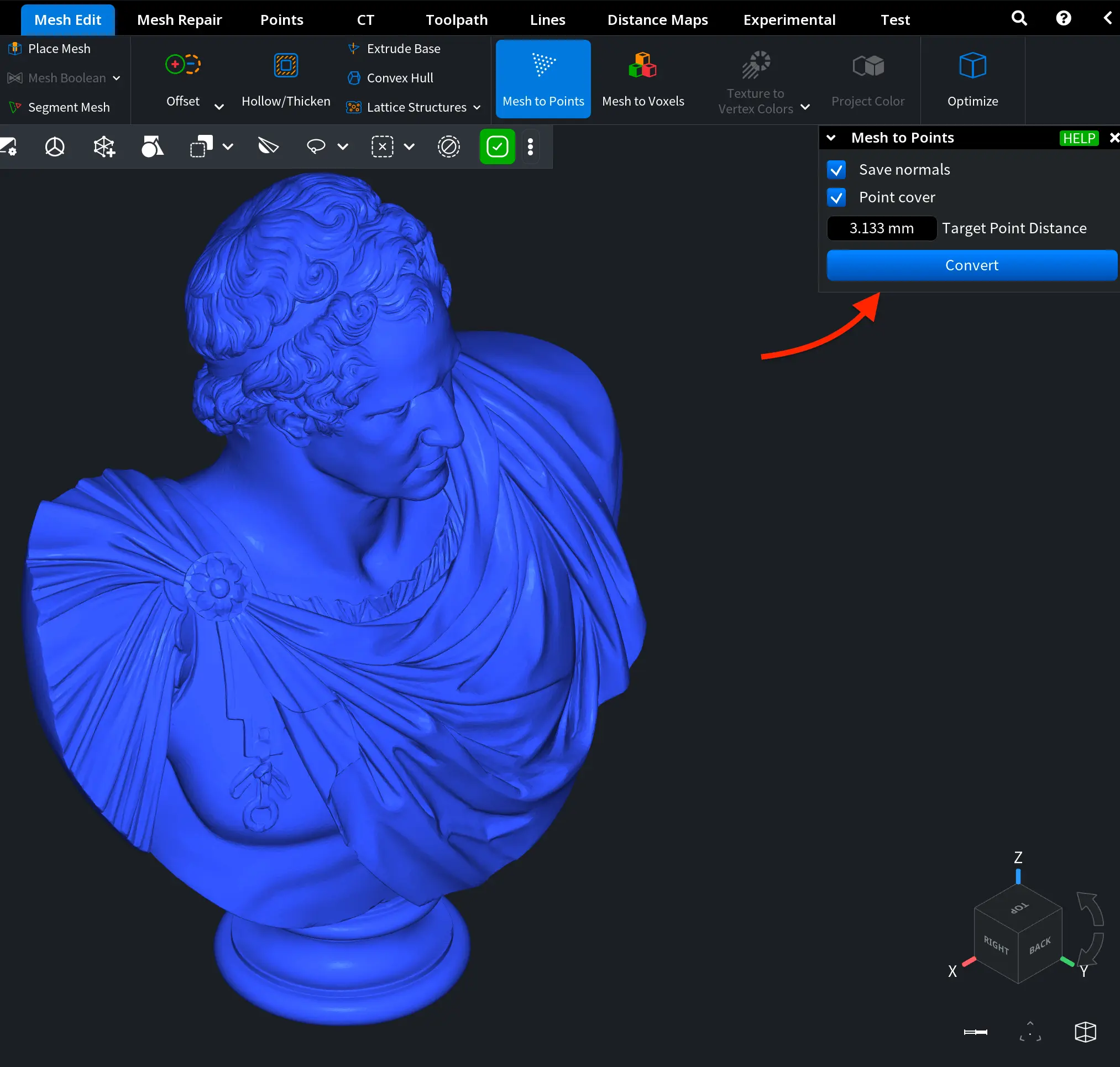
Two main settings are available:
- Save Normals, turned on by default, ensures that the generated points retain normal vectors derived from the original mesh surface. This may be useful for shading, visualization, and any workflow that relies on surface orientation information.
- The Point Cover option enables surface-based sampling of the mesh. The density of the generated point cloud is controlled by the Target Point Distance parameter. A smaller value produces a denser point cloud, while a larger value results in fewer points and a lighter dataset.
To execute the operation, click on Convert.
Mesh to Points: Examples
After you click Convert, MeshInspector creates a new object consisting of surface-sampled points based on the selected mesh and the specified Target Point Distance. We performed three tests using different settings.
Baseline Scenario
In the example shown below, the point cloud was generated using the following settings:
- Save Normals is enabled by default
- Point Cover is enabled manually
- Default Target Point Distance, i.e. 3.133 mm
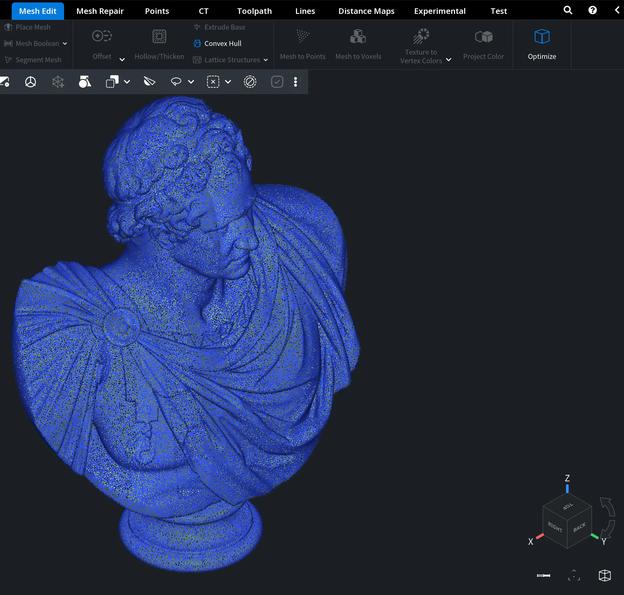
As a result, our point cloud uniformly covers the entire surface of the model. The spacing between points corresponds to the specified Target Point Distance and produces a well-balanced distribution that preserves the overall geometric shape while significantly reducing structural complexity.
Because Save Normals is enabled, each point retains its surface orientation information. This ensures correct shading and makes the point cloud visually consistent with the original mesh when rendered.
All in all, the output maintains the full form and surface detail of the model, but without face or edge connectivity.
Lower Density with Saved Normals
This time, the point cloud was generated using the following settings:
- Save Normals is enabled
- Point Cover is enabled
- Target Point Distance is increased to 10 mm.
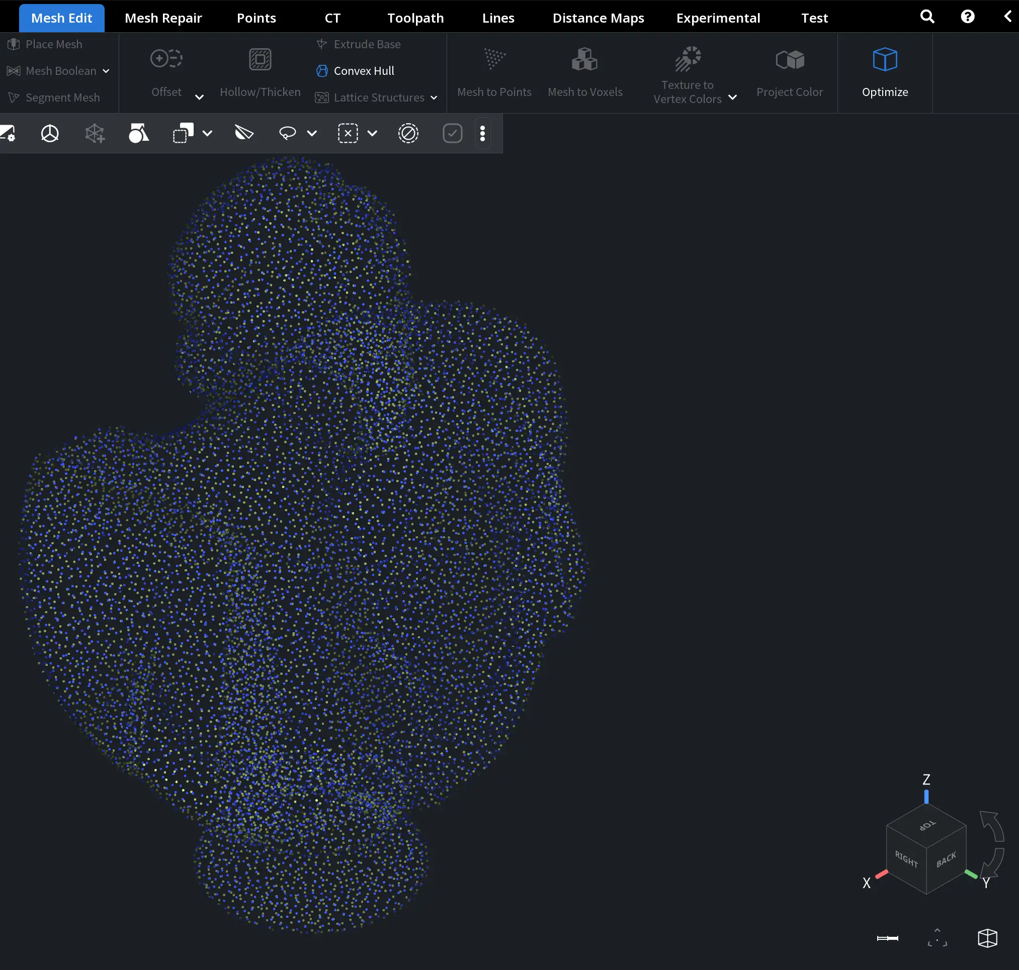
Here, the spacing between neighboring points increases. This means that fewer points are generated across the surface of the model. The point cloud still preserves the overall geometric shape. However, the surface sampling becomes visibly less dense.
Because Save Normals remains enabled, each point retains its surface orientation information. Shading therefore remains consistent with the original mesh, despite the reduced geometric resolution. Overall, the output provides a lighter and more performance-efficient representation of the model, while maintaining its primary form but with reduced surface detail.
Save Normals Disabled
Finally, the point cloud was generated using the following settings:
- Save Normals is disabled
- Point Cover is enabled
- Target Point Distance is set to 5 mm
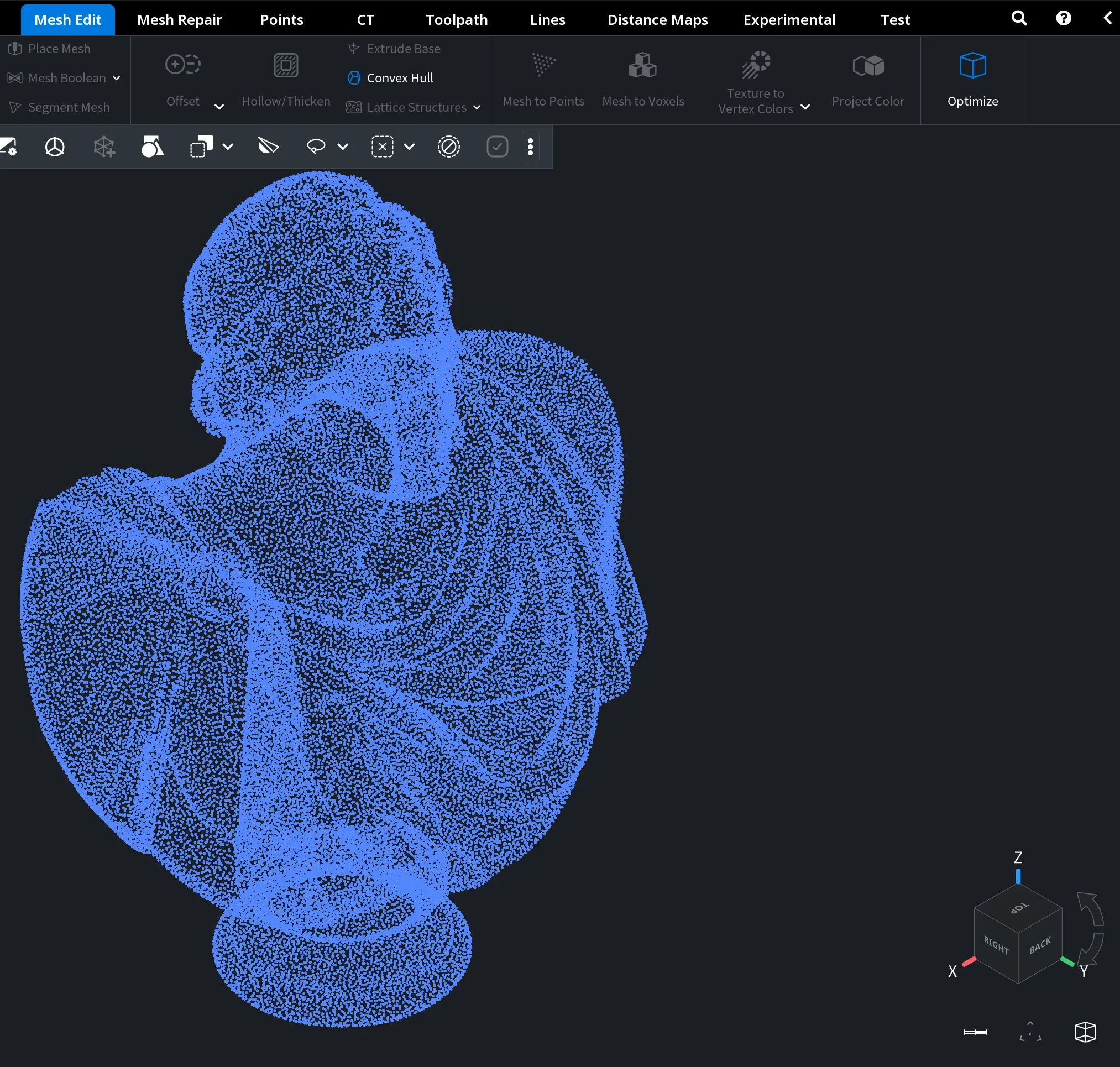
When Save Normals is disabled, the generated points do not retain full surface orientation information. Hence, shading appears uniform and does not reflect the original surface curvature. While the geometric distribution of points remains unchanged, visual depth perception is reduced.