
Loads from YouTube (Google) when you press Play
Mesh Cut & Measure cuts a mesh along a path that you draw on its surface and shows the length of that path. Use it to trim a scan along a line (for example, along the gum line of a dental model), to cut a part off a model where a flat cut does not fit, or to measure a length along a curved surface.
To open it, select one mesh and click Mesh Edit › Mesh Cut & Measure. The same tool is on the Inspect tab.

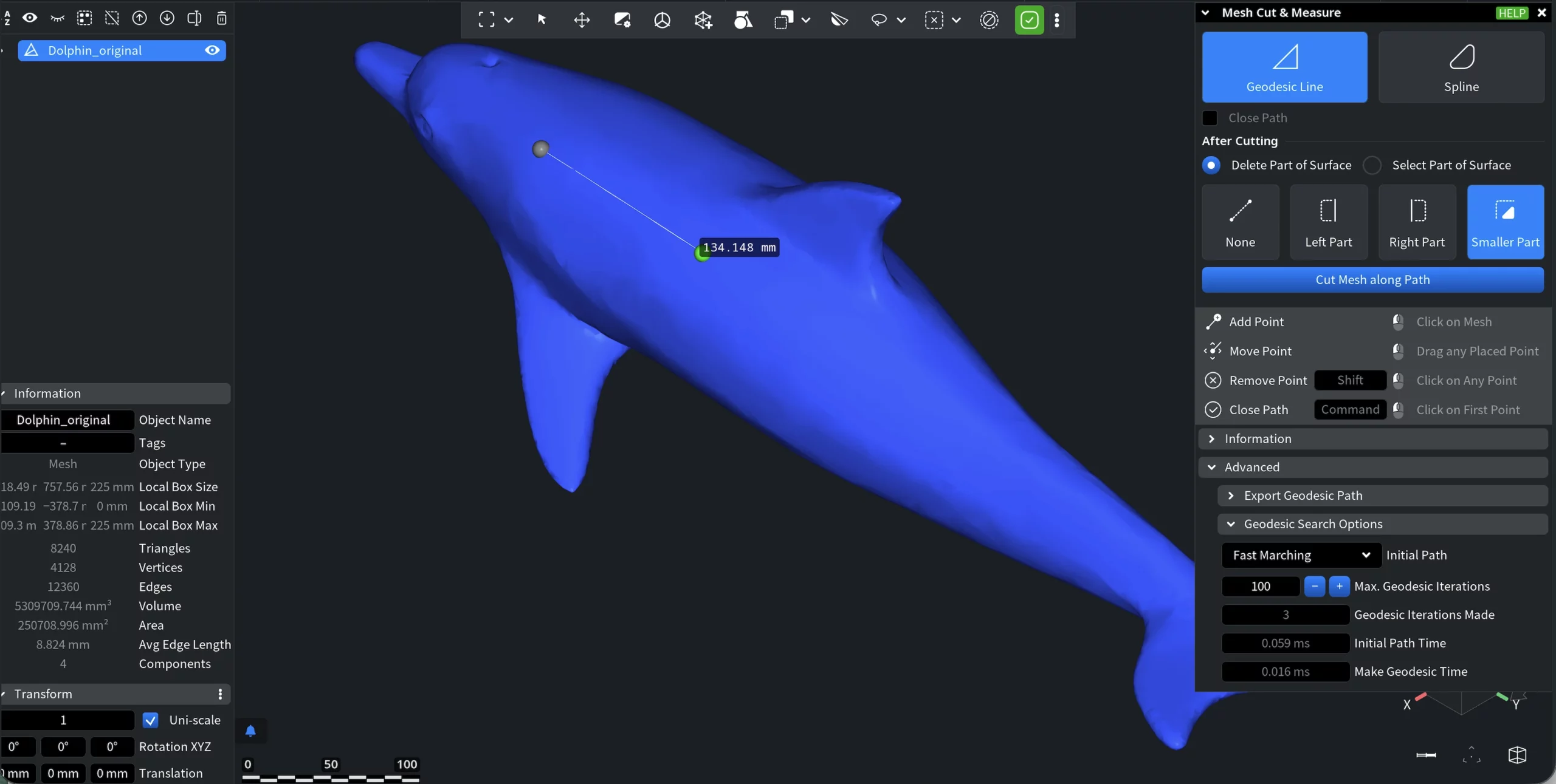
The panel has two path modes at the top, Geodesic Line and Spline:
- Geodesic Line connects each pair of neighboring points by the shortest path on the surface.
- Spline draws a smooth curve through your points. The curve does not follow the shortest path; its shape depends on where you put the points.
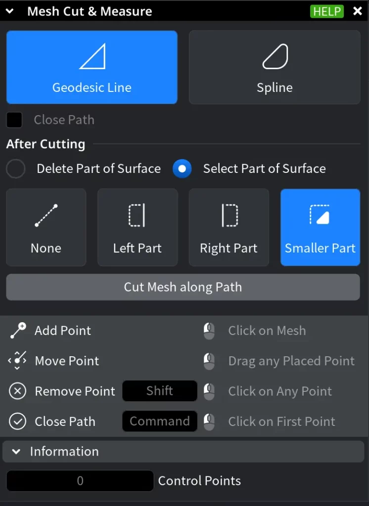
Cutting, the After Cutting options and the Information values work the same way in both modes. Only the way the path is built and some Advanced options differ.
Draw the path
Click on the mesh to add points. The path updates after each change. The Hotkeys section of the panel lists the mouse actions:
| Action | How |
|---|---|
| Add Point | Click on the mesh. The point is added to the end of the path; the last point is green |
| Move Point | Drag any placed point |
| Remove Point | Shift + click a point |
| Close Path | Ctrl + click the first point (Cmd + click on macOS) |
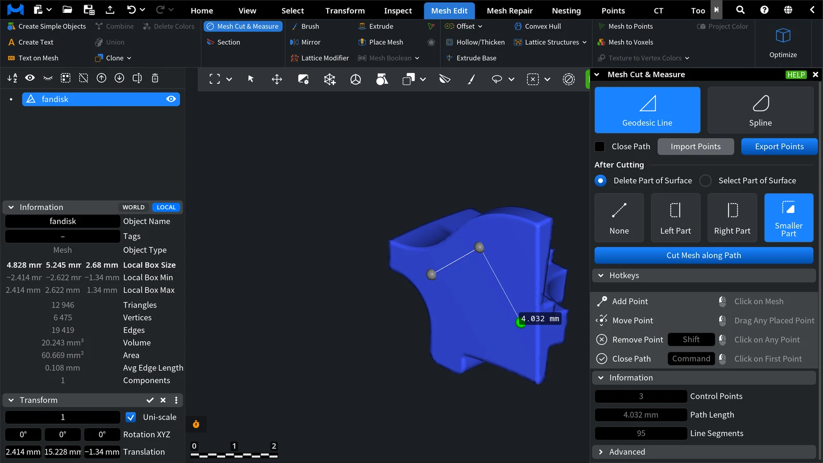
You can also close the path with the Close Path check box. It needs at least three points. After you close the path, you can still move its points, but you cannot add new ones.
Two buttons next to Close Path move the points to and from a point cloud:
- Import Points takes the control points from the selected point cloud. The cloud may have at most 1024 points.
- Export Points creates a new point cloud object from the current control points.
If two points lie on parts of the mesh that are not connected, there is no path between them, and the panel shows No path among current points exists. The points are placed on different connected components.
After Cutting
Choose what happens to the mesh after the cut. First choose the action:
- Delete Part of Surface (the default) deletes the surface on one side of the path.
- Select Part of Surface selects the triangles on one side of the path instead of deleting them.
Then choose the side:
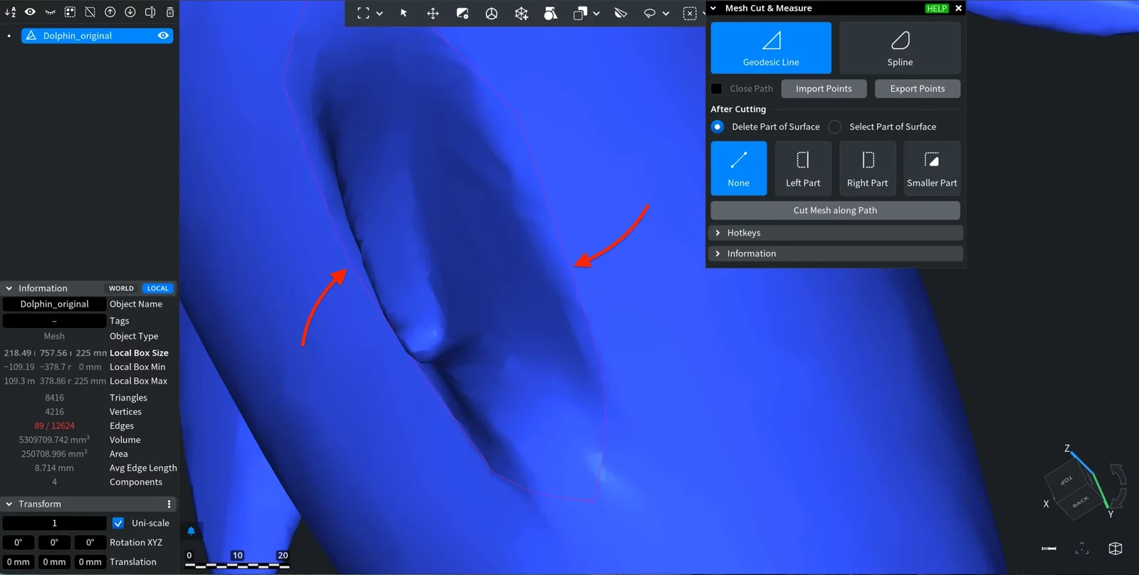
- None does not delete or select any part of the mesh. It only splits the triangles along the path and selects the new edges under it. To get a part as a separate object, use Select Part of Surface instead, as shown in Cut the mesh.
- Left Part and Right Part delete or select the surface to the left or to the right of the path. The direction of the path goes from the first point to the second.
- Smaller Part (the default) deletes or selects the smaller of the two sides.
Information
The Information section shows the path data as you draw:
- Control Points is the number of points you placed.
- Path Length is the length of the whole path through all points, measured along the surface. The same value is shown next to the last point in the viewport.
- Line Segments is the number of triangles the path crosses. Inside each triangle, the path is a straight segment.
Path Length is the length along the surface. For the straight distance between two points, use Measure Distance.
Cut the mesh
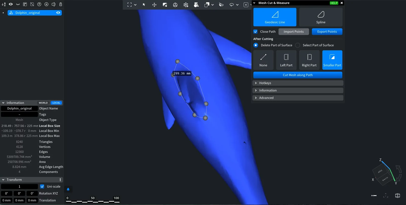
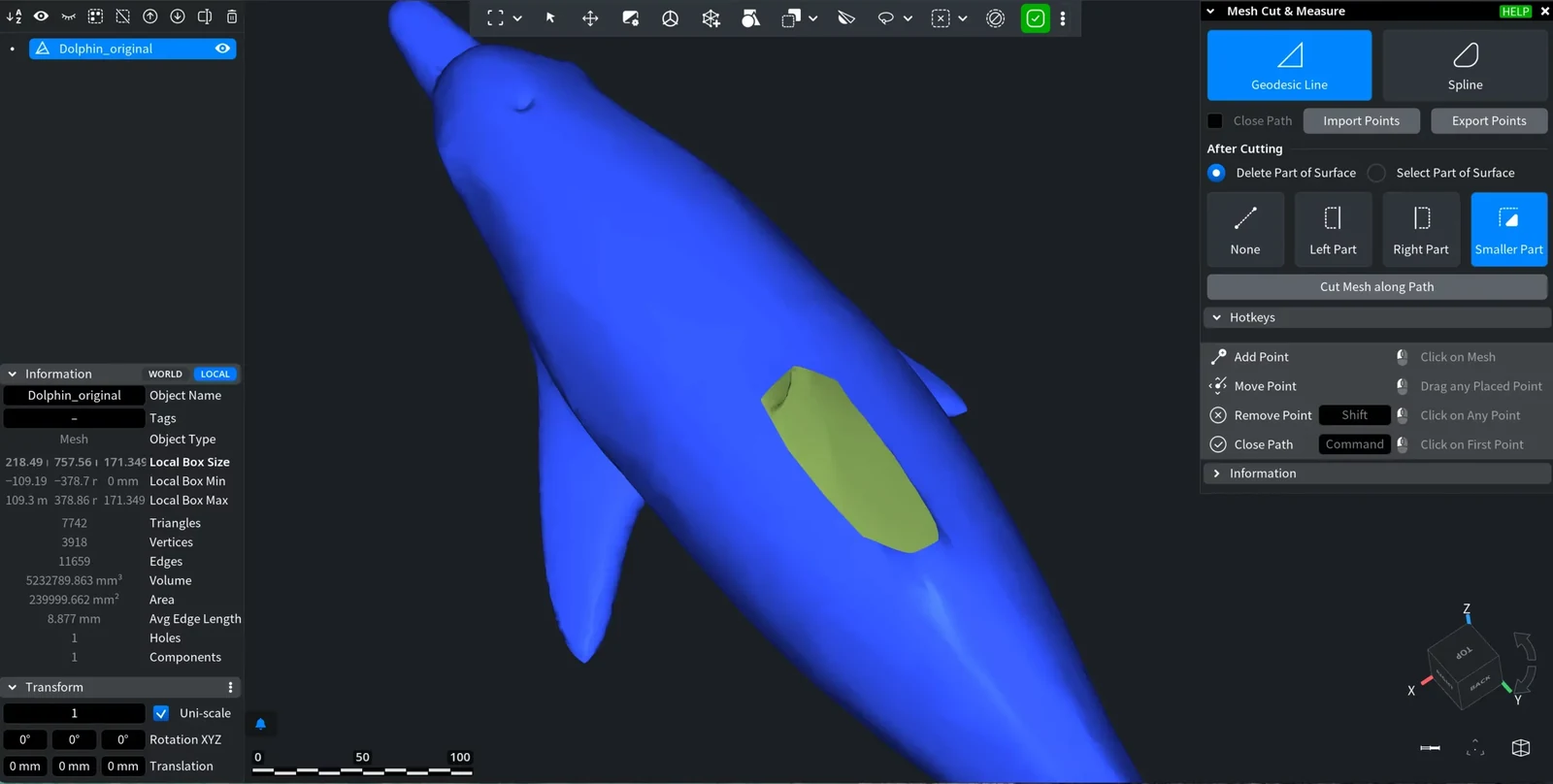
The cut button needs at least two points. In Geodesic Line mode it is called Cut Mesh along Path, in Spline mode Cut Mesh along Spline. MeshInspector splits the triangles along the path and then deletes or selects the part you chose. In the screenshot below, the path is closed, Delete Part of Surface is on, and Smaller Part is chosen.
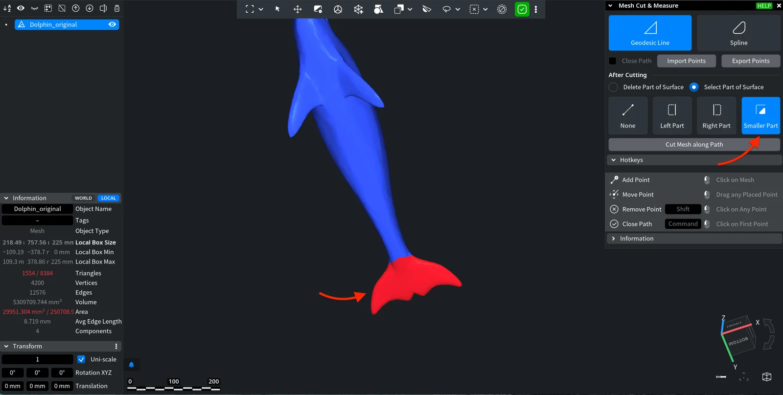
In the next example, Select Part of Surface is on with Smaller Part. The smaller part, the tail, is highlighted in red: all its triangles are selected.
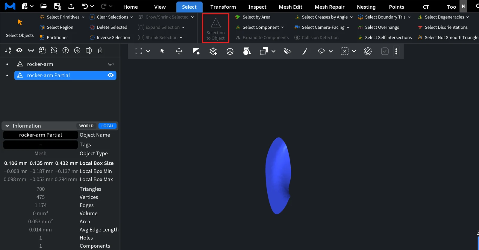
To make a separate object from this selection, click Select › Selection to Object (Selection to Object).
After Delete Part of Surface, the mesh has an open border along the cut. If you need a closed model, for example for 3D printing, close it with Fill Holes or, for a dental model, with Extrude Base as shown in the dental model workflow.
MeshInspector does not cut when the path crosses itself (Mesh cannot be cut because path has intersection.) or when the whole path lies inside one triangle (Cannot cut path that is fully located on single triangle, please subdivide mesh first.).
Advanced settings for Geodesic Line
The Advanced section appears when the path has at least two points.
Export Geodesic Path
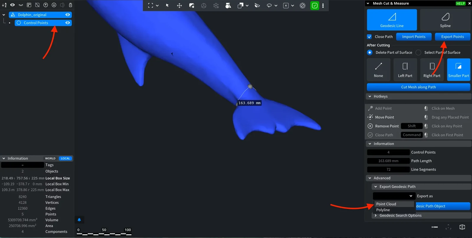
In Geodesic Line mode, this section of Advanced is called Export Geodesic Path. Create Geodesic Path Object adds the current path to the scene as a new object. Choose its type in Export as first:
- Point Cloud (the default) creates a point cloud with normals along the path.
- Polyline creates a lines object.
The new object appears in the Scene tree, and you can edit or export it on its own.
Geodesic Search Options
These options control how MeshInspector builds the path on the surface.
Initial Path is the method for the first approximation of the path between two points:
- Dijkstra bidir. is fast in general, but may not find the shortest path.
- Dijkstra A* is the fastest for nearly straight paths, but can be slower when the path is far from a straight line.
- Fast Marching (the default) is usually closer to the shortest path, but takes longer.
Max. Geodesic Iterations is the maximum number of steps that refine the initial path into the final geodesic path. The default is 100.
When the path has exactly two points, three more values show how the path was built:
- Geodesic Iterations Made is the number of refining steps actually done.
- Initial Path Time is the time spent on the initial path.
- Make Geodesic Time is the time spent on refining it.
Spline
In Spline mode, the points define a smooth curve, and MeshInspector projects it onto the surface to get the cutting line. After that, cutting, deleting and selecting work as in Geodesic Line mode.
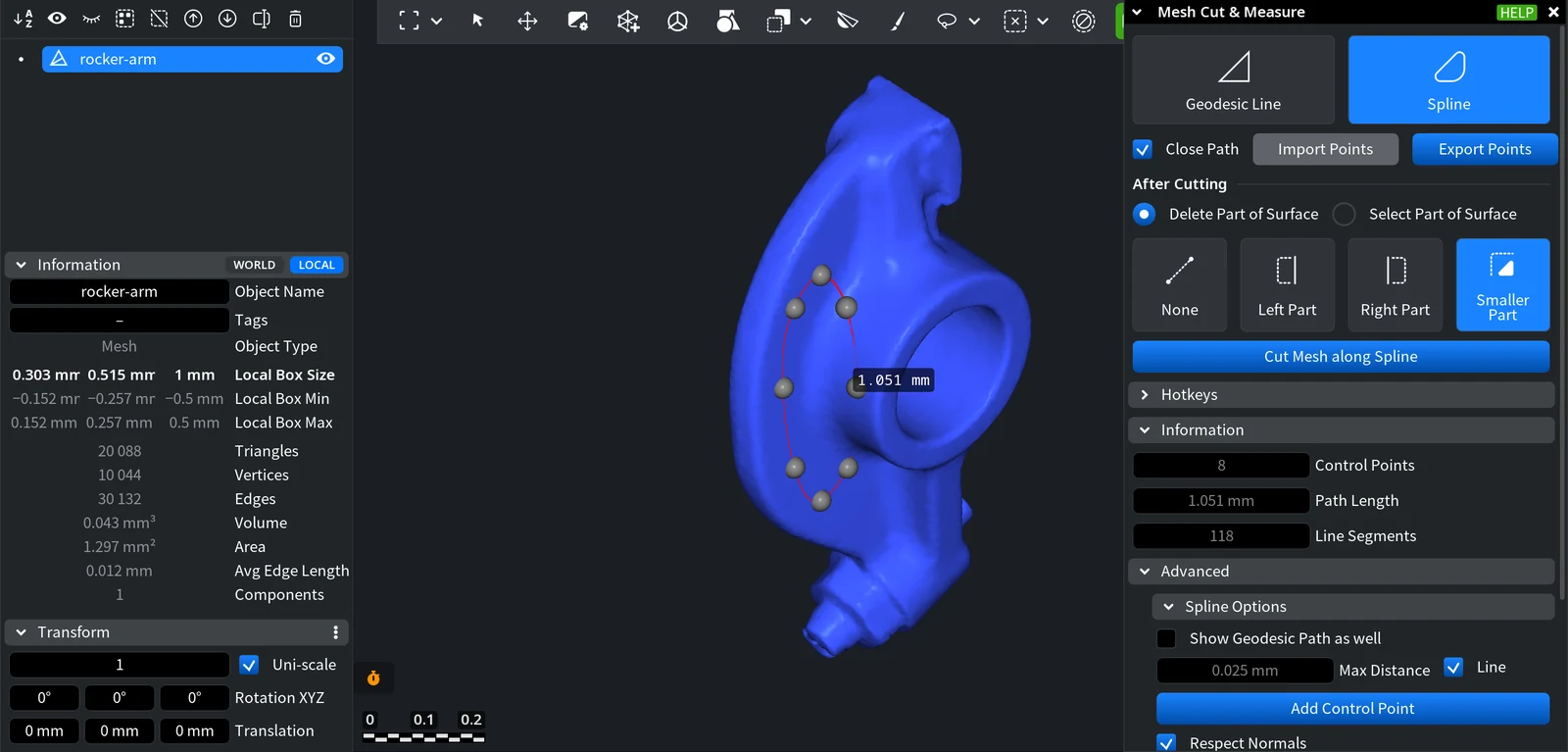
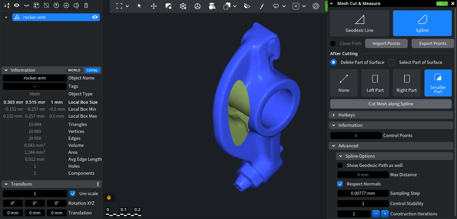
When you click Cut Mesh along Spline, the edge of the cut follows the smooth curve.
Spline Options
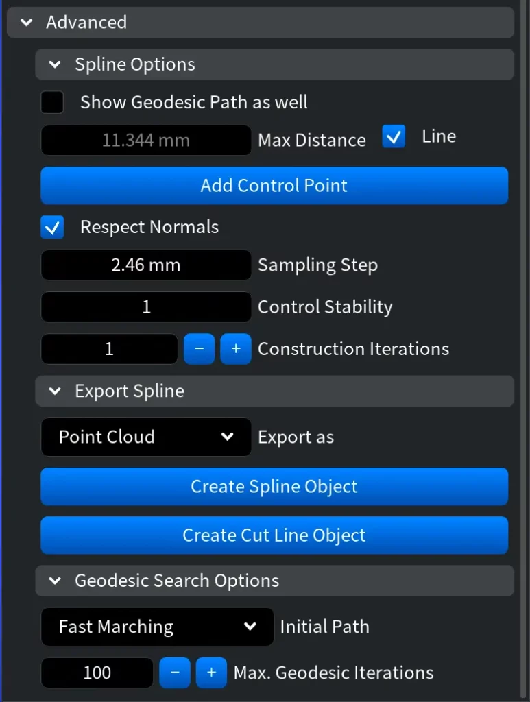
In Spline mode, Advanced has a Spline Options section:
| Option | What it does | Default |
|---|---|---|
| Show Geodesic Path as well | Shows the geodesic path between the points together with the spline | Off |
| Max Distance | A read-only value: the largest distance between the points of the geodesic path and the points of the spline. Turn on Line to show this distance as a segment in the viewport | — |
| Add Control Point | Adds a point on the geodesic path where it is farthest from the spline | — |
| Respect Normals | Makes the spline perpendicular to the mesh normals at the control points | On |
| Sampling Step | MeshInspector adds points between each pair of control points until the distance between neighboring points is smaller than this value | 0.3% of the diagonal of the model's bounding box |
| Control Stability | A positive number. The larger it is, the closer the spline passes to the control points | 1 |
| Construction Iterations | From 1 to 5. More iterations give a better spline but take longer | 1 |
Export Spline
In Spline mode, the export section of Advanced is called Export Spline. Below Export as (Point Cloud or Polyline), it has two buttons:
- Create Spline Object adds a copy of the shown spline to the scene as an object of the chosen type.
- Create Cut Line Object adds the cutting line of the current spline to the scene as a new object.


