Measure Distance is a precision inspection tool that allows you to create exact linear measurements between selected points or supported geometric features in the scene. To start working with it, go to the Inspect tab and click Measure Distance.

Once Measure Distance is activated, a dedicated panel will open.
Measurement Modes
Measure Distance supports multiple measurement modes:
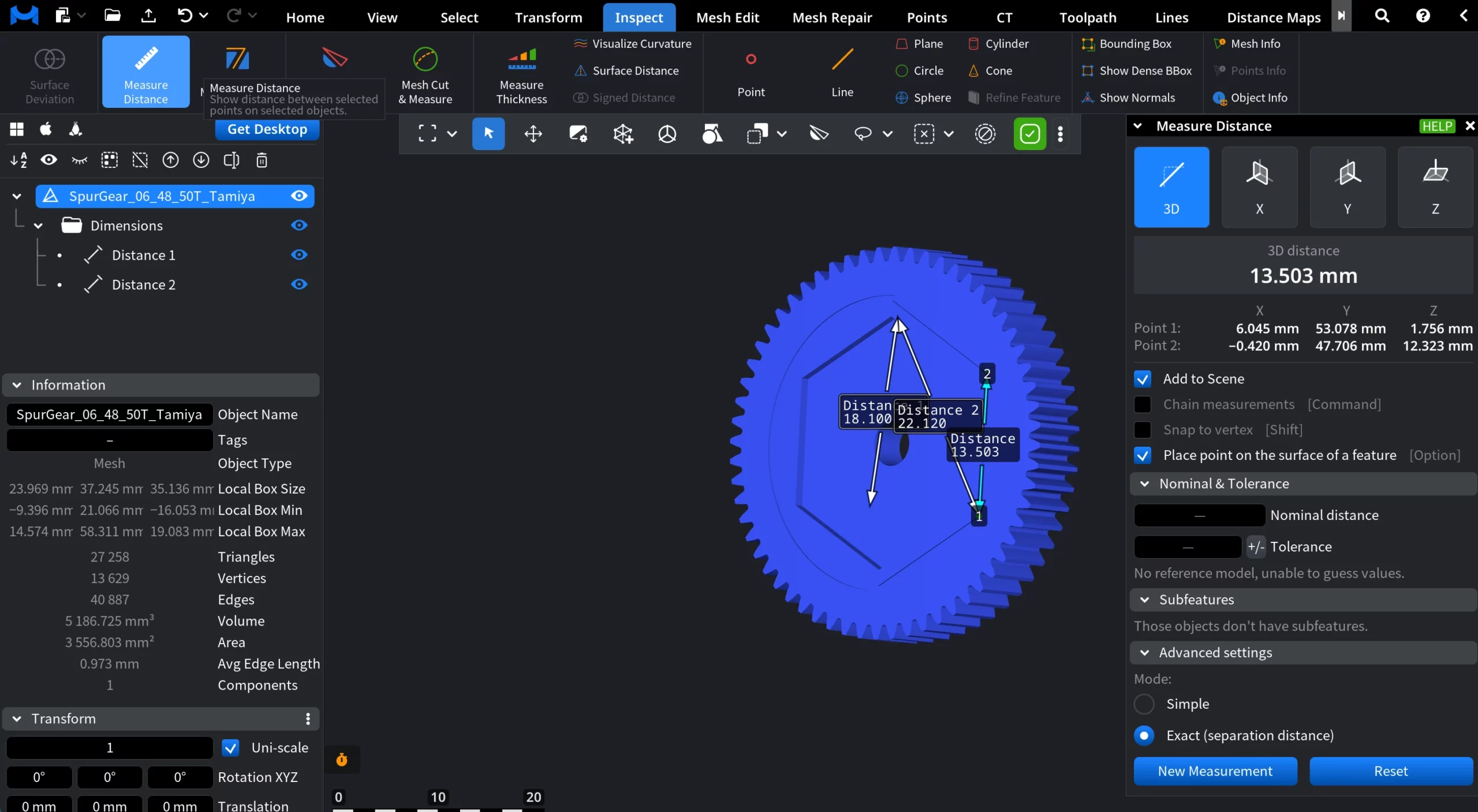
3D measures the true Euclidean distance between two selected points or features in 3D space.
X / Y / Z measure the distance projected onto the selected axis only.
Point Coordinates
When a distance measurement is created, the Measure Distance panel also displays the coordinates of the two picked points:
- Point 1 stands for the coordinates of the first selected point
- Point 2 stands for the coordinates of the second selected point
For each point, its X, Y, and Z coordinates are shown in the current model units and coordinate system.
Measurement Settings
Add to Scene controls whether measurements are kept.
- When it is enabled, each finished measurement stays in the scene as a separate distance object.
- When it is disabled, every new measurement replaces the previous one.
Chain measurements, that can be activated by clicking Command, controls continuous measuring.
- If on, each new point starts from the previous endpoint, creating a chain of distances.
- If off, each measurement is independent and starts fresh.
Snap to vertex, that can be activated by clicking Shift, controls point precision.
- When on, measurement points snap exactly to mesh vertices.
- When off, points can be placed freely on surfaces.
Place point on the surface of a feature, that can be activated by clicking Option, controls how picked points attach to geometry.
Nominal and Tolerance
This section lets you compare a measured distance against a target value and an allowed deviation. It becomes active after a distance measurement is created
- Nominal distance is the expected (design) value of the distance.
- ± Tolerance is the allowed deviation from the nominal value.
Subfeatures
The Subfeatures section exposes logical reference points of selected geometric features. Subfeatures appear only when you select a supported feature.
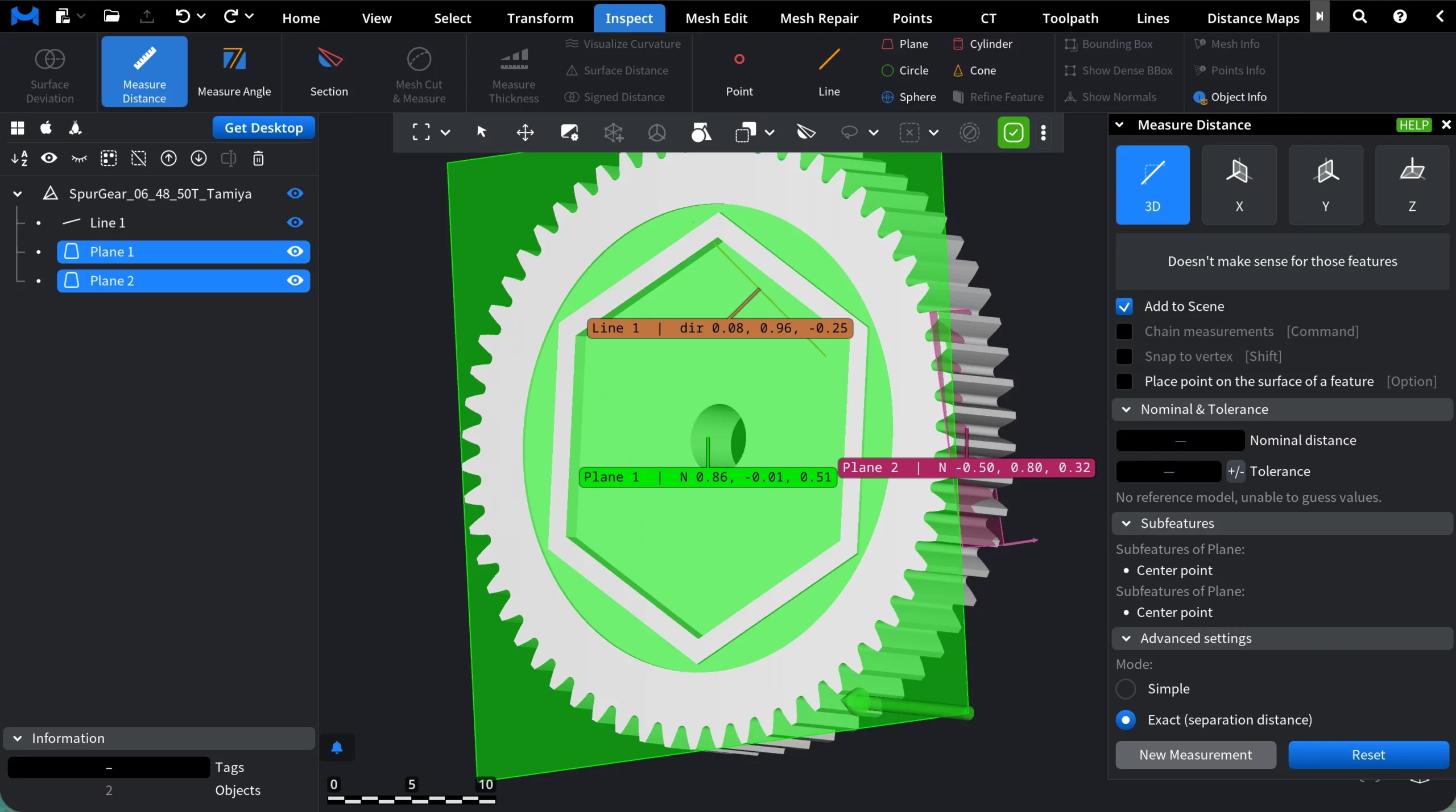
Advanced settings
Advanced settings define how the distance itself is computed and how measurements are managed.
Mode
- Simple measures the straight-line (Euclidean) distance between the selected points or features.
- Exact (separation distance) computes the true minimum separation between the selected features, taking their actual geometry into account.
Commands
New Measurement starts a new distance measurement session.
Reset clears the current measurement state.