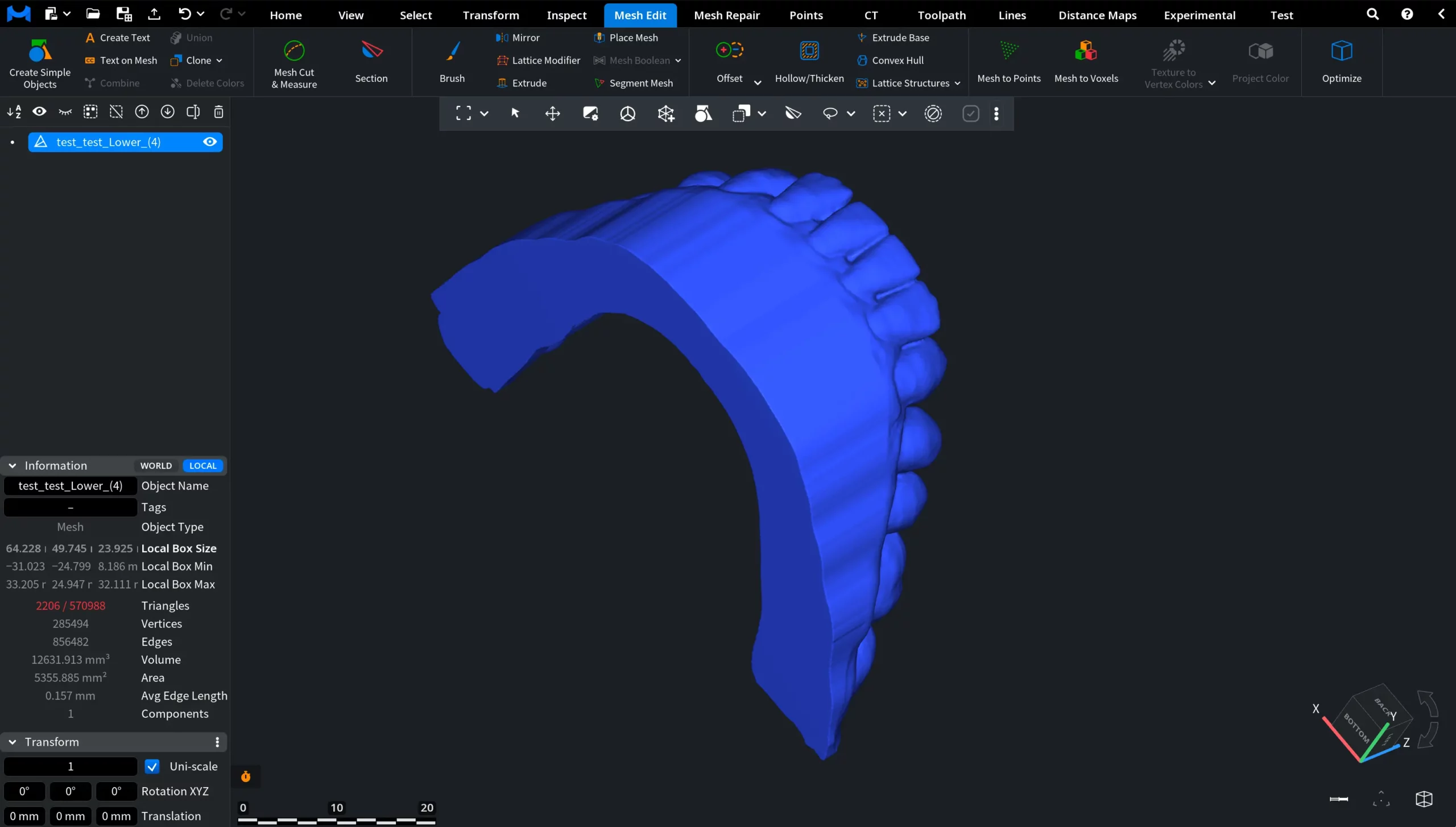
Intraoral scans and other organic meshes are typically not ready for 3D printing immediately. To name a few issues, they might contain excess gingival geometry, have open boundaries, lack a stable printable base, and be fully solid, which leads to excessive material usage.
For efficient additive manufacturing, your model must be cleaned, closed, aligned, hollowed, and filled with a lightweight internal structure. This guide demonstrates a complete workflow for preparing a dental model for 3D printing using MeshInspector.
Step 1. Trim Excess Geometry
Our goal is to remove unnecessary gingival regions and create a clean boundary for base generation. Trimming ensures that only the relevant portion of the scan remains.
How to do it:
- Go to Mesh Edit, then to Mesh Cut & Measure.
- Select Spline mode.
- Enable Delete Part of Surface and Smaller Part.
- Place control points along the gingival contour.
- Close the path.
- Click Cut Mesh along Spline.
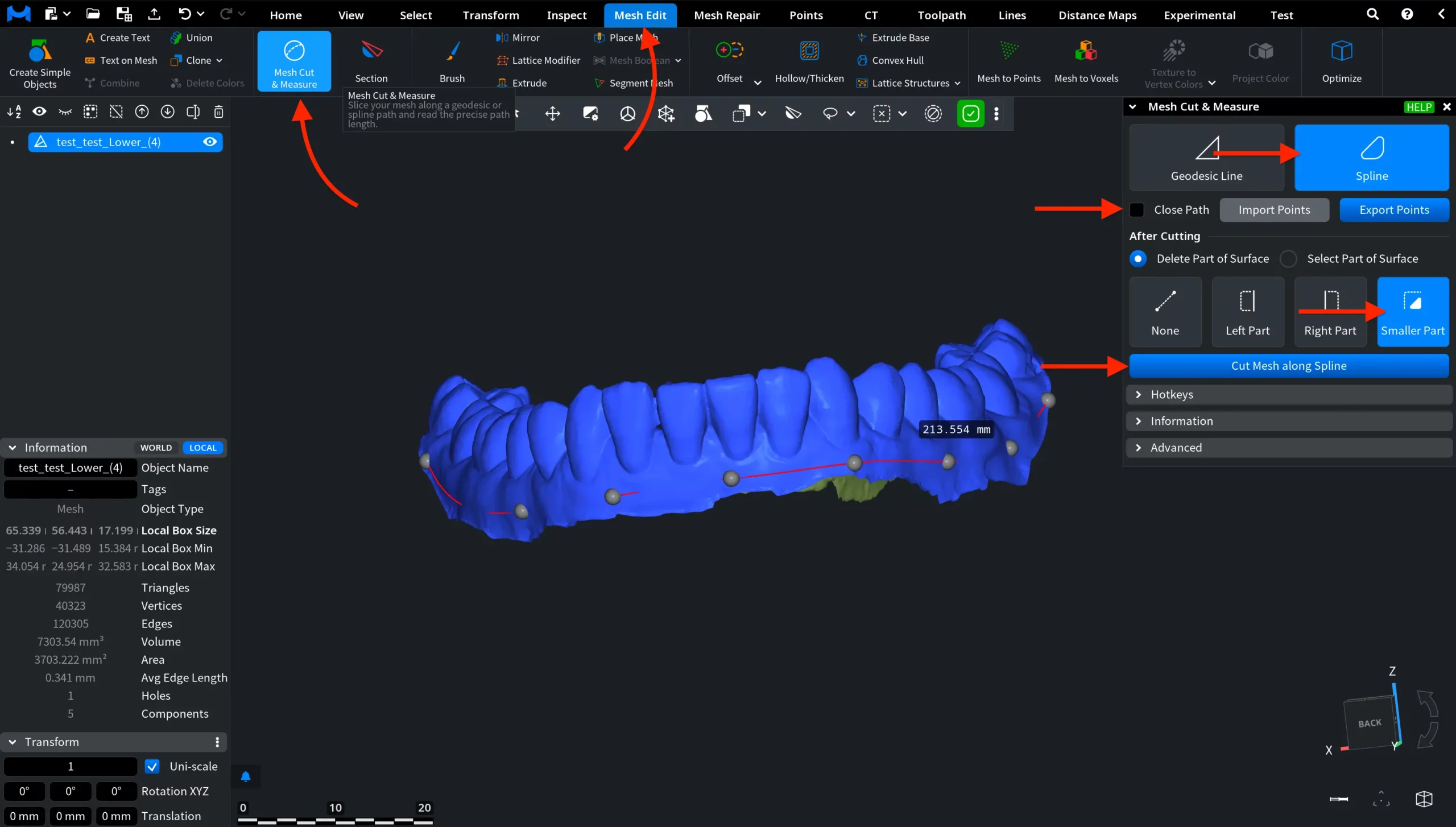
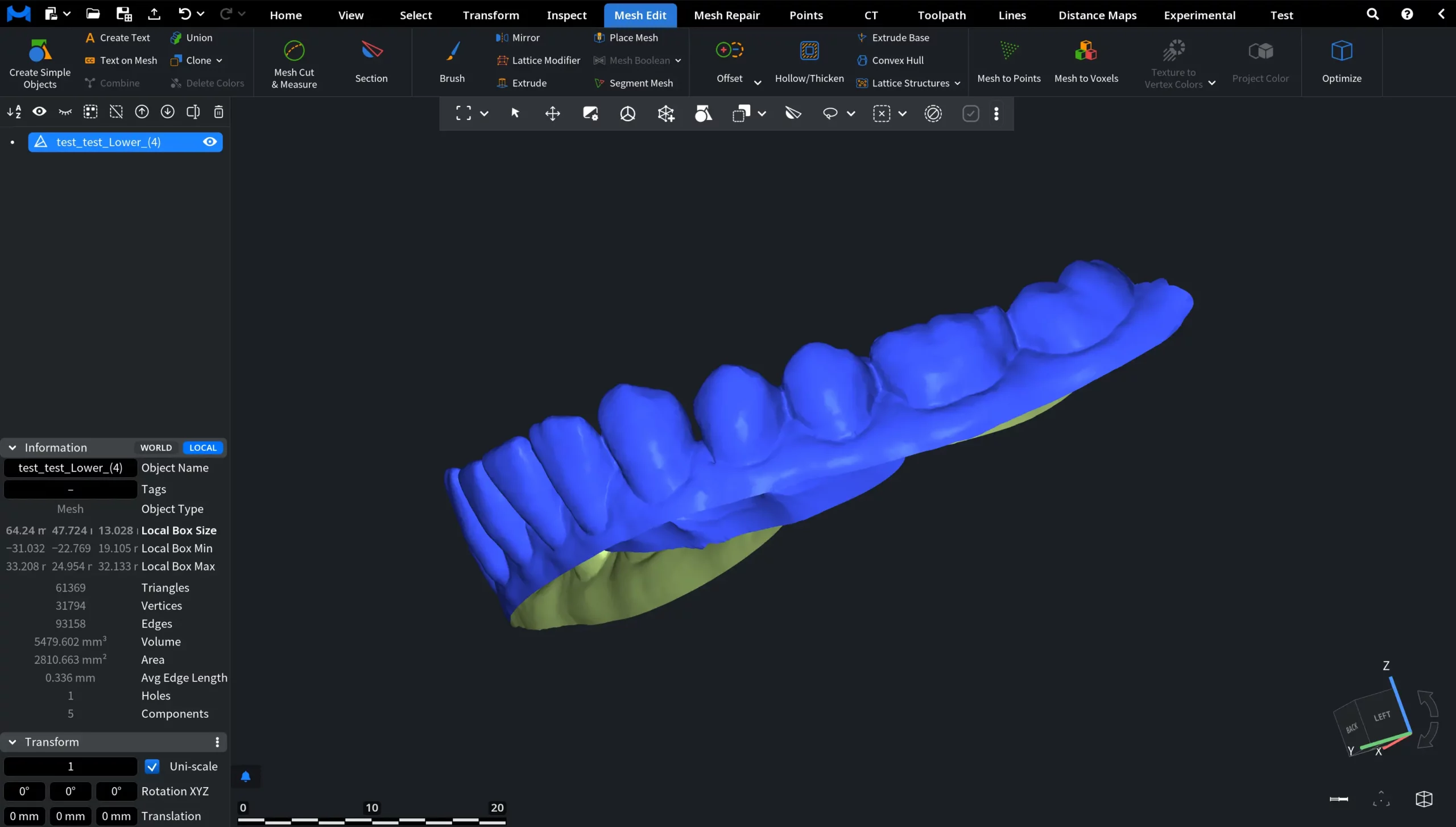
After trimming, the model has a clean, well-defined open boundary.
Step 2. Select the Boundary
Our next objective is to define the contour from which the printable base will be generated. For this, we need to select boundary triangles that will determine where extrusion will occur.
How to do it:
- Switch to the Select tab.
- Click Select Boundary Tris.
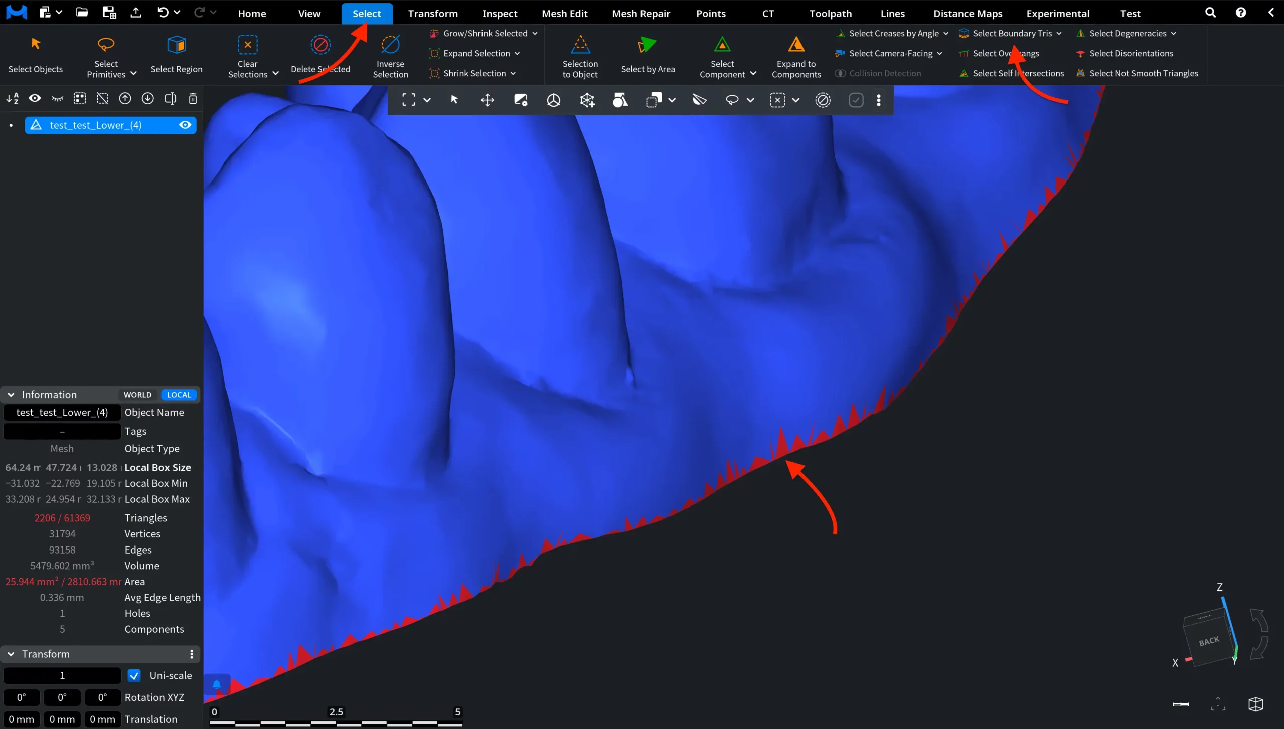
The open edge of the mesh is automatically highlighted.
Step 3. Generate a Printable Base
After that, we should convert the open scan into a closed, printable model. The Extrude Base tool creates a flat support surface and closes the mesh. The red arrow displayed in the viewport indicates the Print Direction. Note that the base is generated in the opposite direction of the red arrow.
How to do it:
- Go to Mesh Edit, then Extrude Base.
- Define the Print Direction. Our recommendation is to click Direct to Camera, then Find Optimal Direction.
- Confirm the red arrow shows the correct Print Direction.
- Enable Fix Undercuts for Selection Only.
- Click Extrude Base.
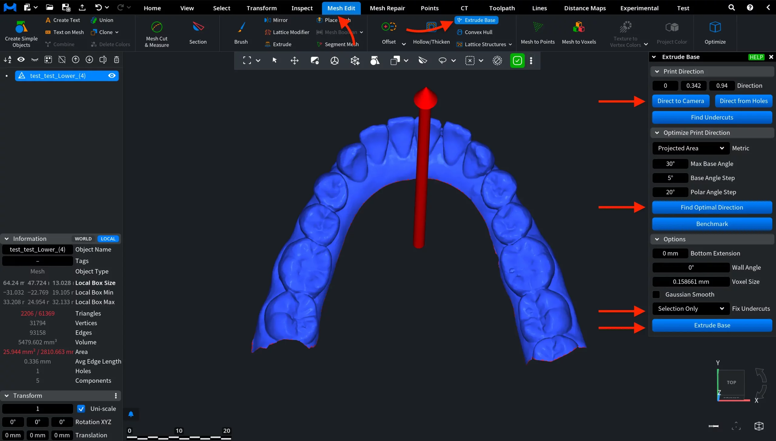
The model is now closed with a stable base.
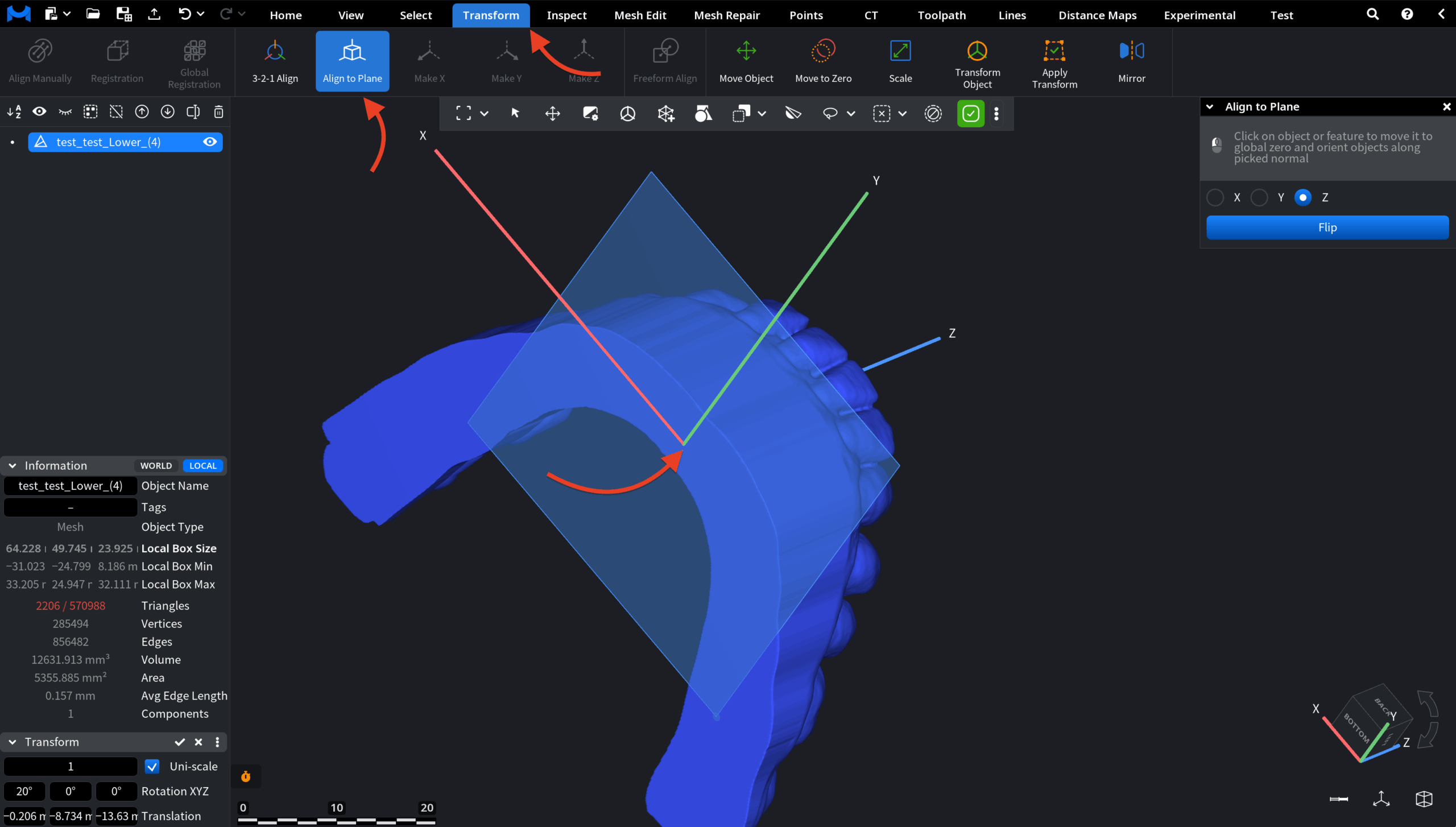
Step 4. Align the Model
Next, it would be reasonable to ensure correct orientation relative to the global coordinate system. Proper alignment is important for predictable printing and further processing.
How to do it:
- Go to Transform, then Align to Plane.
- Click on the flat base surface.
The model is automatically aligned to the global plane.
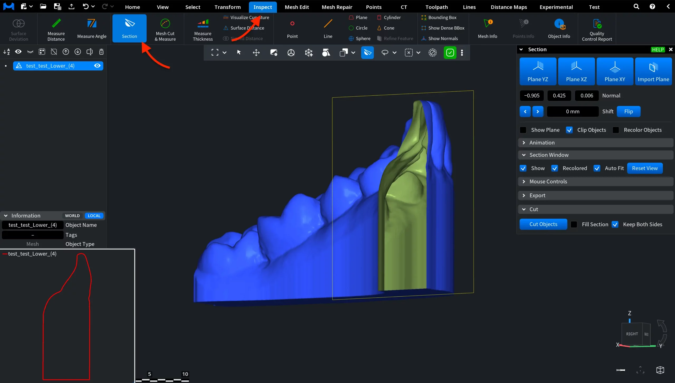
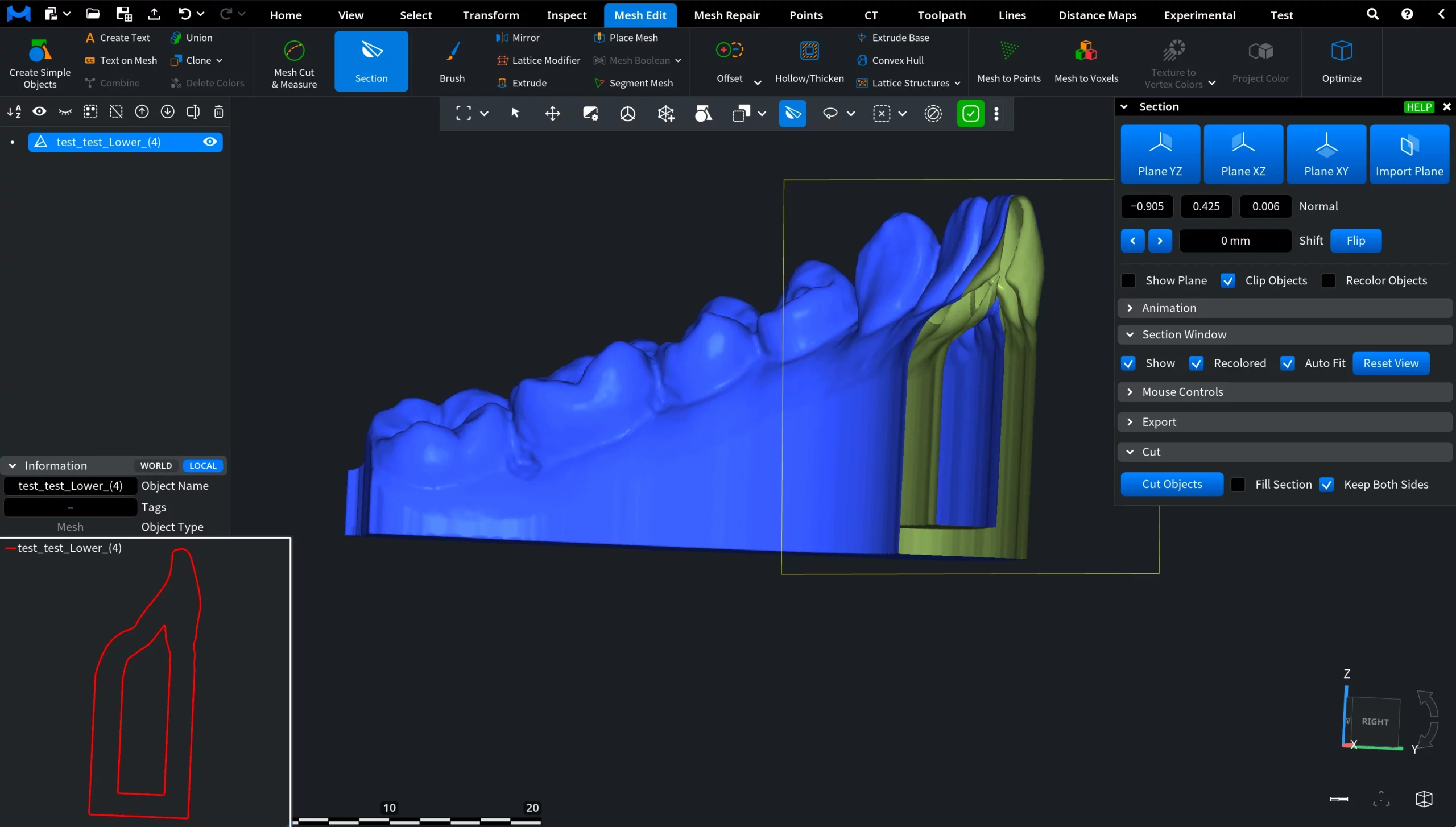
Step 5. Inspect the Interior
Now, we check the internal structure before hollowing. By default, the model is completely solid, which increases material consumption during printing.
How to do it:
- Activate Section under Mesh Edit.
- Move the section plane through the model.
In our case, the model is fully solid. This is quite typical.
Step 6. Hollow the Model with a Defined Wall Thickness
To reduce material usage while maintaining structural strength, we create a uniform wall thickness that enables internal lattice filling.
How to do it:
- Go to Mesh Edit, then choose Offset.
- Select Thickening mode.
- Set the value. In our case, it is –2 mm.
- Keep Resolution: Standard.
- Click Apply.
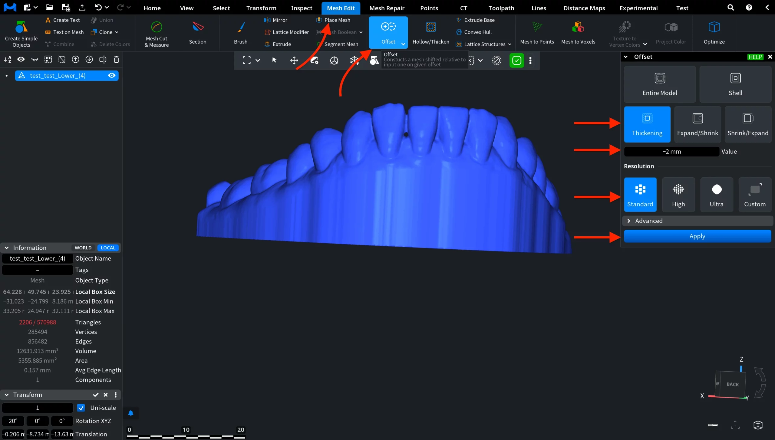
The model is now hollow with a uniform 2 mm wall thickness. You can use the Section tool again to confirm the cavity.
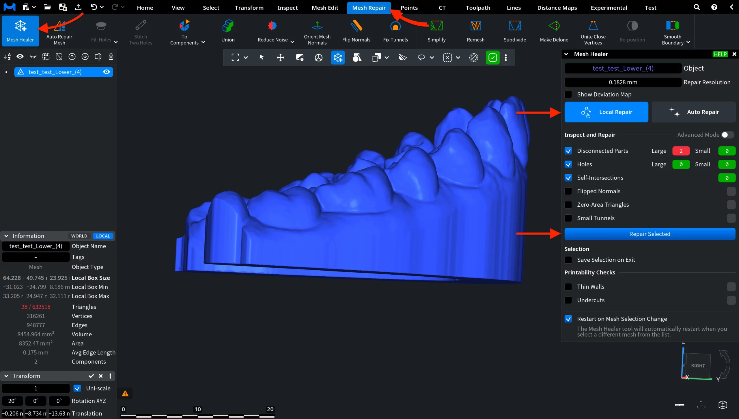
Step 7. Heal the Mesh
Ensure the geometry is valid before lattice generation. For that, run Mesh Healer under the Mesh Repair tab to automatically fix issues that could prevent the lattice from being generated.
How to do it:
- Launch Mesh Healer.
- Click Repair Selected in the Local Repair mode.
- Confirm there are no critical errors.
Step 8. Generate the Internal Lattice
It is time to create a lightweight internal structure for additive manufacturing. The Lattice Structures tool reduces material usage while preserving strength.
How to do it:
- Go to Mesh Edit, then Lattice Structures.
- Set Filling Mode: Inner.
- Under Kind, select TPMS (Triply Periodic Minimal Surface).
- Choose Thick Gyroid.
- Click Apply.
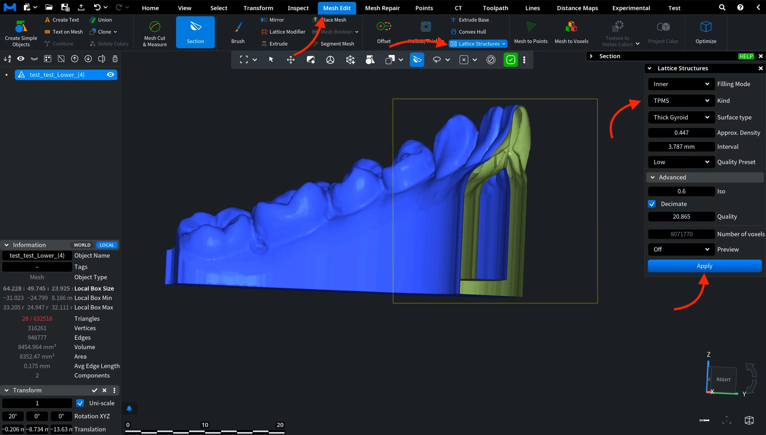
The gyroid lattice is generated inside the hollow region. You can use the Section tool to inspect the internal structure.
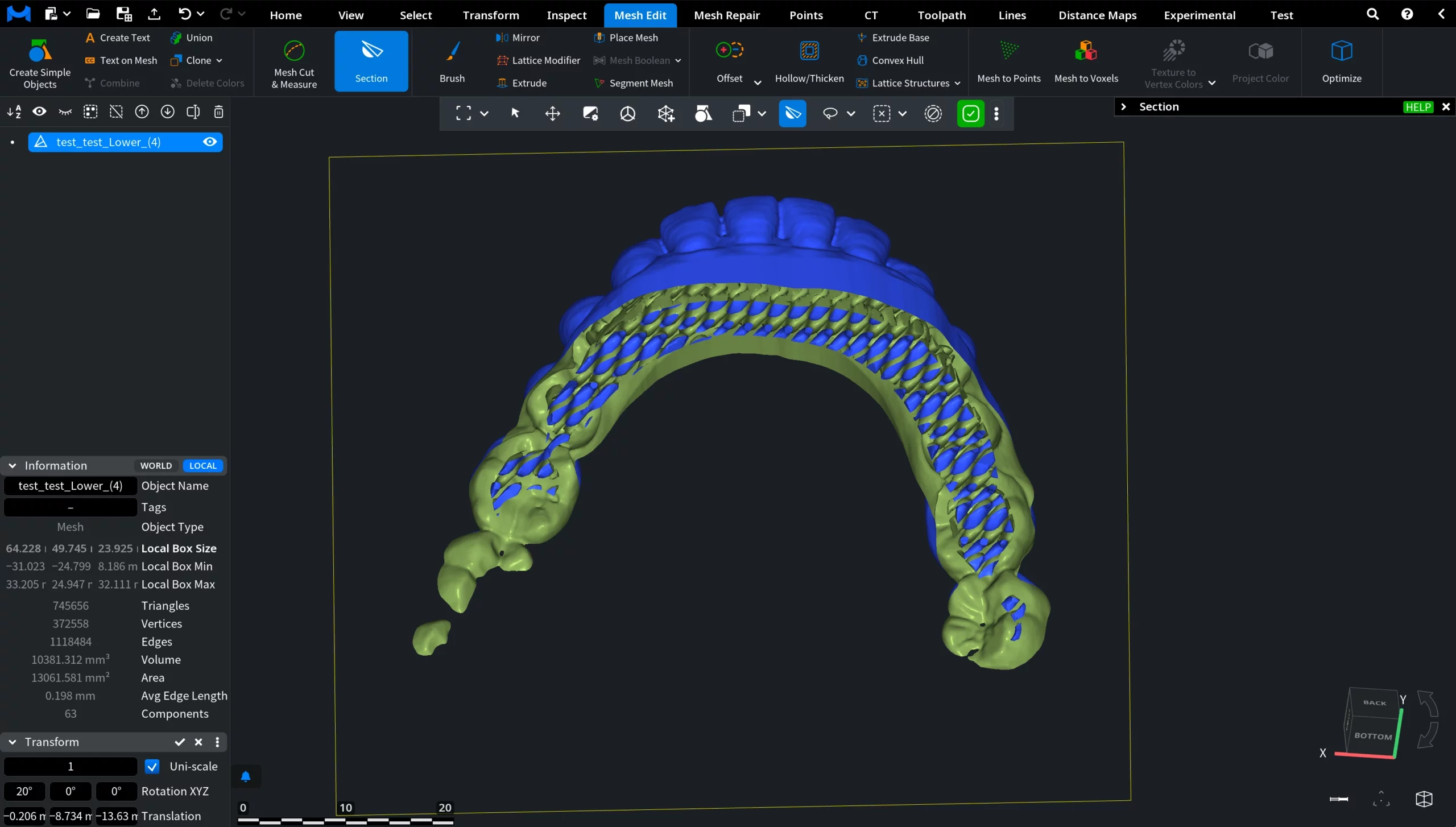
Result
Through this workflow, we gradually achieved the following results:
- A trimmed model.
- A closed printable base.
- Proper global alignment.
- A 2 mm wall thickness.
- A healed mesh.
- An internal gyroid lattice structure.
The model is now fully optimized for effective 3D printing. This is how you can reduce material usage while maintaining mechanical stability.