Z-Compensate is a tool for 3D printing: it shifts every vertex whose normal has a negative projection on the Z axis, that is, every vertex of a surface that faces down, along the Z axis. The triangles of the mesh stay the same; only the vertices move. Use it before printing when the down-facing surfaces of your prints come out too low, for example when holes and slots across the build direction come out too small.
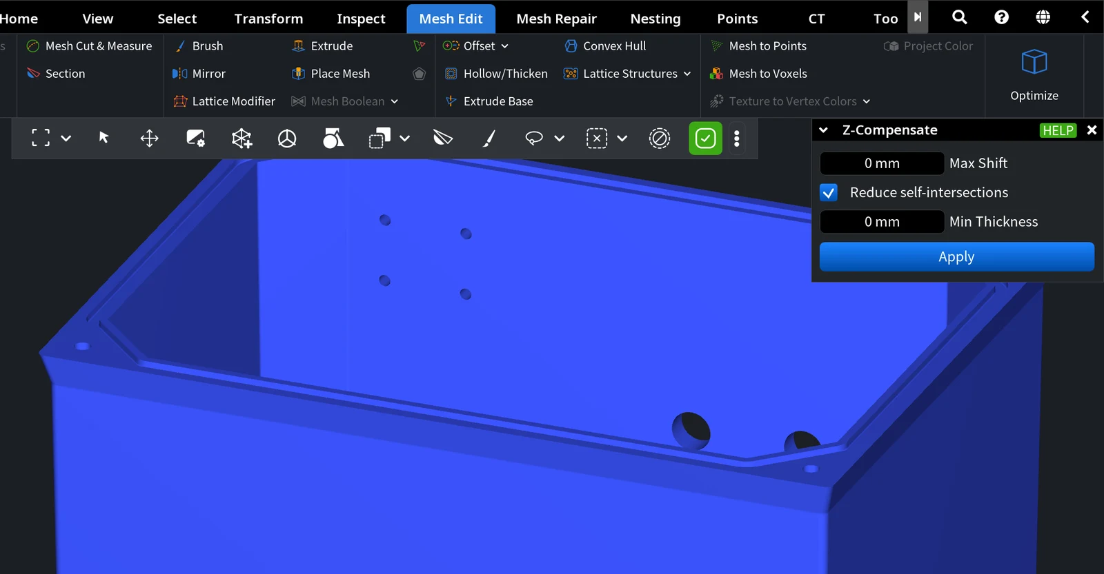
To open the tool, select one or more meshes, go to Mesh Edit, click the arrow next to Offset and choose Z-Compensate. It is one of the tools of the Offset family.

When you need it
The typical case is resin (SLA and DLP) printing. The light that cures a layer also cures some liquid resin beyond it. Under a surface that faces down (the underside of an overhang, the ceiling of a horizontal hole or slot, the bottom of a part printed on supports) there is liquid resin, so a thin extra skin cures there, and the surface ends up lower than in the model. The error is small, but it matters where sizes must match: a hole in a part printed upright comes out smaller than designed, and a pin or an insert no longer fits.
Z-Compensate removes this skin from the model in advance: it moves every down-facing surface up, into the part, so that after printing the surface is where you designed it. Surfaces that face up or exactly sideways do not move.
Z-Compensate: Parameters
| Parameter | What it does | Default |
|---|---|---|
| Max Shift | The shift of the parts of the mesh that are orthogonal to the Z axis and face against it (straight down). Other downward-facing parts move less, depending on the angle between the vertex pseudo-normal and the Z axis. | 0 mm |
| Reduce self-intersections | Limits the movement of each vertex to reduce self-intersections in the mesh. | Off |
| Min Thickness | Shown when Reduce self-intersections is on. A vertex does not move closer than this distance to another triangle. | 0 mm |
How the shift is computed
According to the MeshLib source code of the tool:
- A vertex moves only if its pseudo-normal points down (has a negative Z component). Vertices of surfaces that face up or exactly sideways do not move.
- The vertex moves up, in the +Z direction, by Max Shift multiplied by the downward part of its normal: by the full Max Shift on a surface that faces straight down, and by less on an inclined surface.
- With Reduce self-intersections on, the shift of a vertex is limited so that it stays at least Min Thickness away from the triangles above it. If moving a vertex would flip one of its triangles, the shift is halved, up to ten times.
- The Z axis is the Z axis of the mesh data. If you rotated the object with the transform controls, apply the rotation to the mesh first with Transform › Apply Transform, so that the tool uses the new orientation.
How to use Z-Compensate
- Orient the model so that its Z axis is the vertical axis of the print, and apply the transform if needed.
- Select the mesh (or several meshes) and open Z-Compensate.
- Enter Max Shift. To limit self-intersections, turn on Reduce self-intersections and set Min Thickness.
- Click Apply (or press Enter). The vertices move at once, there is no preview, and the panel closes. To get the original mesh back, use Undo (Ctrl+Z, or Cmd+Z on macOS).
How to choose the value
The size of the extra skin depends on your printer, resin and exposure settings, so measure it on a test print instead of guessing:
- Print a test part without compensation, in the orientation and with the settings you use for the real part. A good test part has a horizontal slot or a horizontal hole of a known size.
- Measure the printed feature along the build direction: the height of the slot or the vertical diameter of the hole.
- Subtract the printed size from the designed size. The difference is how far the ceiling of the slot or hole grew down. Enter it as Max Shift: a ceiling that faces straight down moves up by exactly this value.
- Run Z-Compensate on the real part, print it and measure the same feature again. Measure again when you change the resin or the exposure settings.
Worked example
We tested the tool on the CAD housing from the MeshInspector demo files (312 × 136 × 223 mm, 39,730 vertices, Z axis as in the file) with Max Shift 0.5 mm and Reduce self-intersections off:
- 20,137 vertices moved, about half of the mesh; the other vertices are on surfaces that face up or sideways.
- The lowest point of the housing moved up by 0.40 mm, not 0.5 mm, and only one vertex moved by the full 0.5 mm. The top of the housing did not move, so the height along Z went from 222.71 mm to 222.31 mm.
- The reason is the coarse CAD mesh: a flat face of a CAD export often has no vertices inside it, only at its edges. The normal of an edge vertex is averaged with the walls next to it, so the vertex counts as inclined and moves less.
- After we subdivided the mesh so that no edge was longer than 3 mm (143,184 vertices), 9,747 vertices, the ones inside flat down-facing faces, moved by the full 0.5 mm.
So for a CAD part with large flat faces, run Mesh Repair › Subdivide first; otherwise the compensation is smaller than Max Shift near the edges of these faces.
Limits
- The tool moves every down-facing surface of the whole mesh, including a flat bottom the part stands on, so the part also becomes lower. You cannot limit it to a selected area.
- The vertices move only up, along the Z axis of the mesh; there is no shift sideways and no correction of surfaces that face up.
- Moving surfaces closer to the surfaces above them can make thin walls thinner or cause self-intersections, for example in small text. Turn on Reduce self-intersections and set Min Thickness to keep a gap, and check the result with Select Self Intersections before printing.
See which areas move
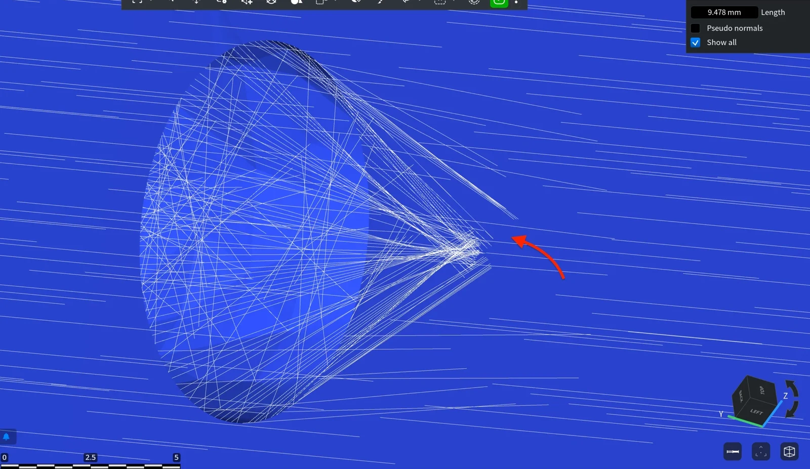
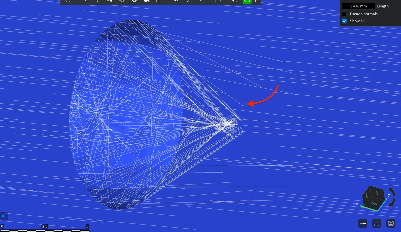
To see which areas are affected, turn on Inspect › Show Normals: the vertices whose normals point down are the ones that move. In this example, Max Shift is set to 2 mm, Reduce self-intersections is on, and Min Thickness is 0.5 mm. The first picture shows a hole in a scanned part before Z-Compensate:
After Apply, the downward-facing vertices in the same area have shifted along Z: