
Create Simple Objects adds basic shapes to the scene: a cube or parallelepiped, a cylinder or cone, a sphere, a torus, an arrow and a prism. You need them as tool bodies and reference bodies: a cylinder to drill a hole with Mesh Boolean, a box to cut off or keep part of a model, a plate to put a model on, or a simple part of known size to test a workflow. The same panel also creates points, segments and text labels.
To open it, click Mesh Edit › Create Simple Objects.

The panel has two modes:
- Interactive: draw a cube, a cylinder or a sphere with the mouse.
- Use Parameters: enter exact sizes and the position for any of the six shapes.
After you create an object, move or rotate it with Transform Object, and join it to a model with Union or subtract it with Mesh Boolean.
Interactive
In Interactive mode you create a Cube, a Cylinder or a Sphere directly in the viewport: choose the shape, then drag with the left mouse button to set its size, orientation and position. The panel shows the current dimensions while you drag:
- Cube: the sizes along X, Y and Z
- Cylinder: the diameter and the length
- Sphere: the radius
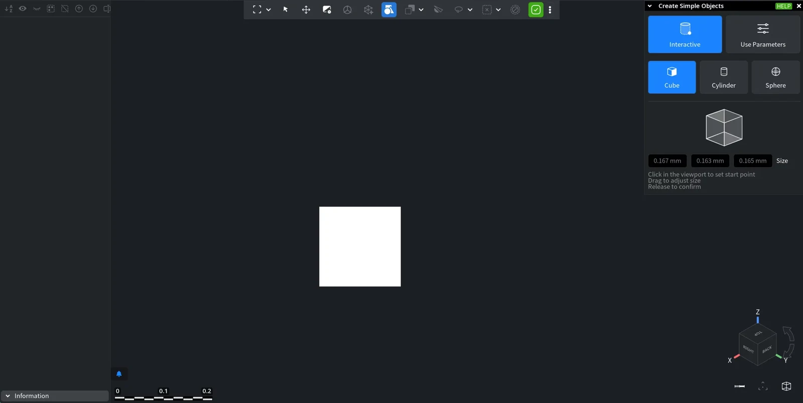
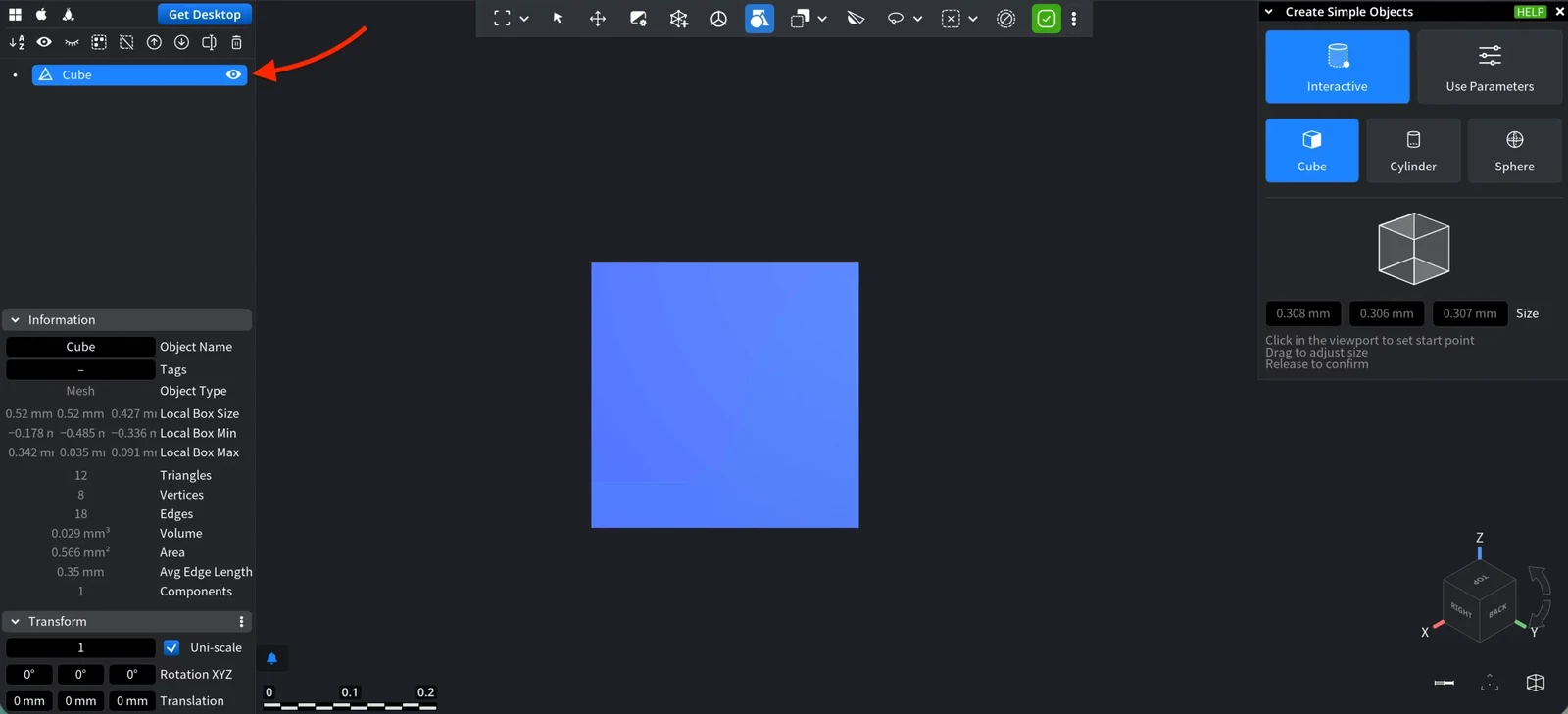
Release the mouse button to add the object to the scene and the Scene tree. The white preview turns into a normal colored object.
Use Parameters
Use Parameters creates an object from exact values. On the Objects tab choose Cube, Cylinder, Sphere, Torus, Arrow or Prism, set its parameters, and click Create.
All shapes share these fields:
| Field | What it does |
|---|---|
| Center | The position of the center of the object (X, Y, Z). Default: 0, 0, 0 |
| Name | The name of the new object, for example Cube0 or Cylinder0 by default |
| Add Feature Object | Also creates a measurement feature of the same shape. Shown for a Sphere, and for a Cylinder when both diameters are equal (or one of them is 0, then it is a cone). See Features |
| Show Preview | Shows a white preview of the object in the viewport before you click Create. Off by default |
| Create | Adds the object to the scene |
Cube and Parallelepiped
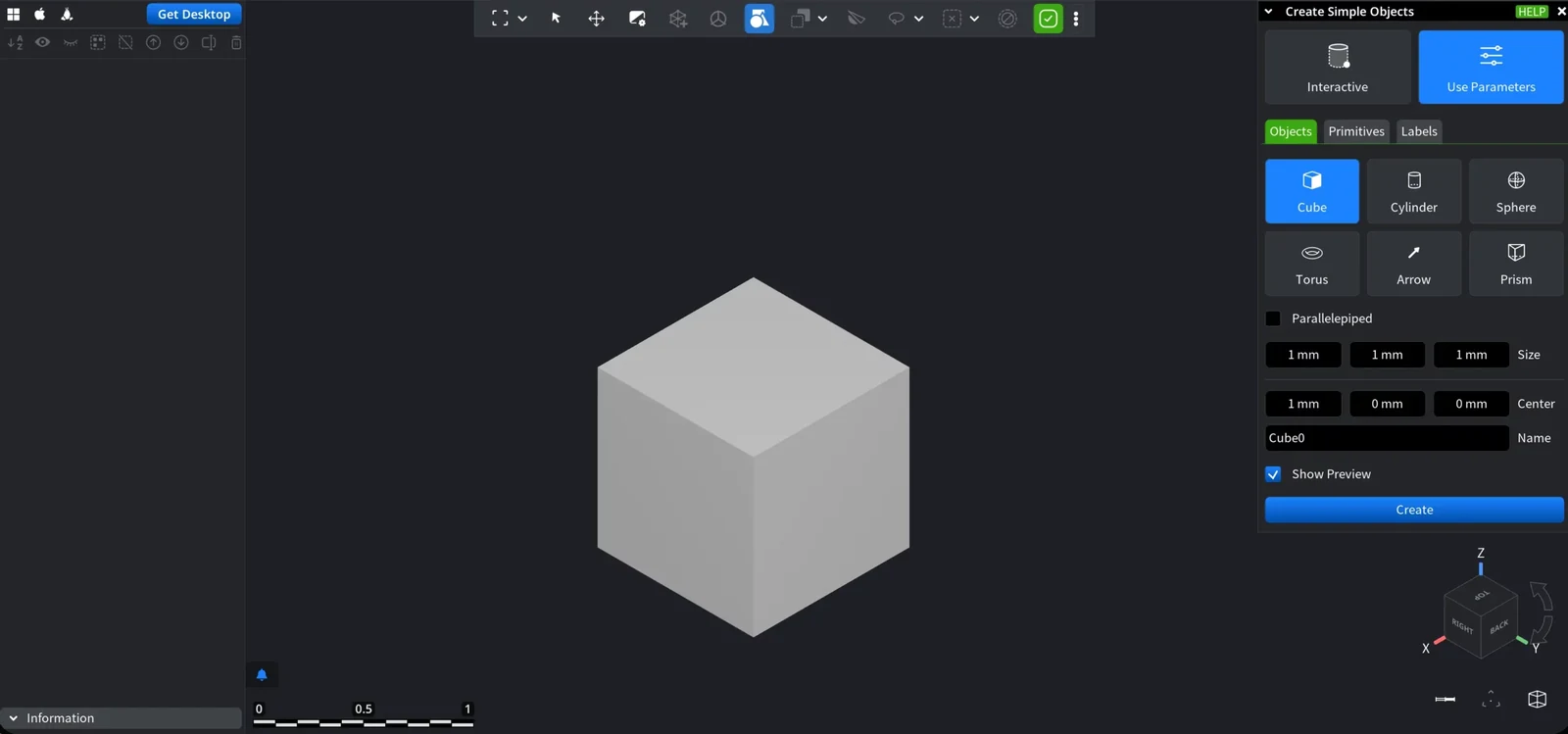
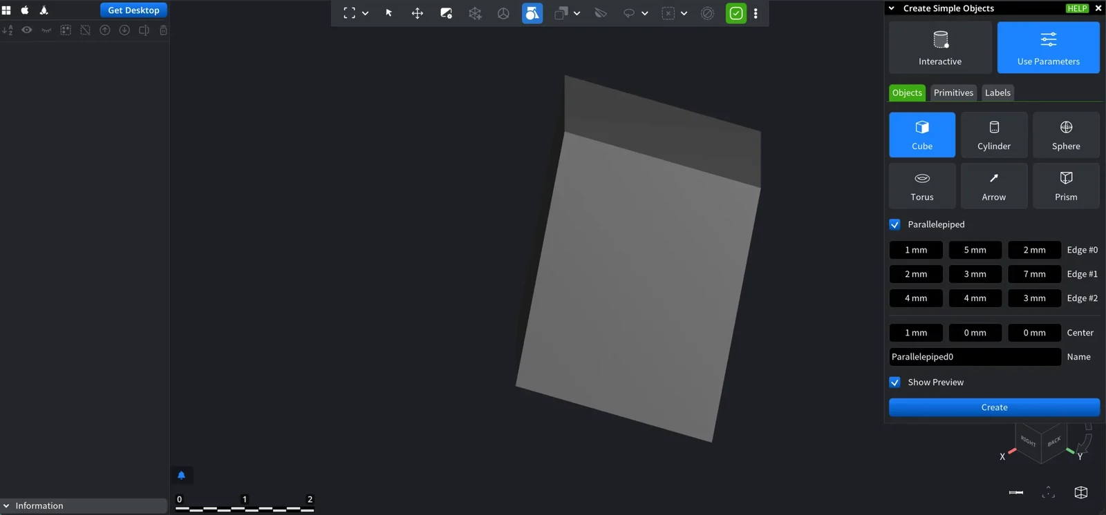
- Size sets the edge lengths along X, Y and Z. Default: 1 × 1 × 1 mm.
- Parallelepiped replaces Size with three separate fields Edge #0, Edge #1 and Edge #2, one for each edge of a rectangular box.
Cylinder
The cylinder axis is the Z axis.
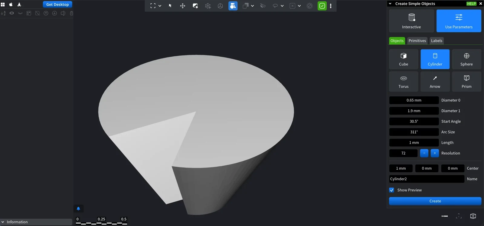
| Parameter | What it does | Default |
|---|---|---|
| Diameter 0, Diameter 1 | The diameters of the two ends. Different values give a cone or a truncated cone | 1 mm |
| Start Angle | Where the cylinder surface starts around the axis | 0° |
| Arc Size | How much of the full circle the surface covers. 360° gives a full cylinder, smaller values a segment | 360° |
| Length | The length along the axis | 1 mm |
| Resolution | The number of segments around the circle (3 to 4000). More segments give a smoother surface | 72 |
Sphere
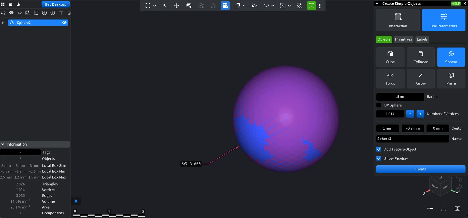
- Radius sets the radius of the sphere.
- UV Sphere builds the sphere from rings and meridians. Then Horizontal Resolution sets the number of segments around the sphere and Vertical Resolution the number from top to bottom.
- With UV Sphere off, Number of Vertices sets the density of the mesh (16 to 100 000).
Torus
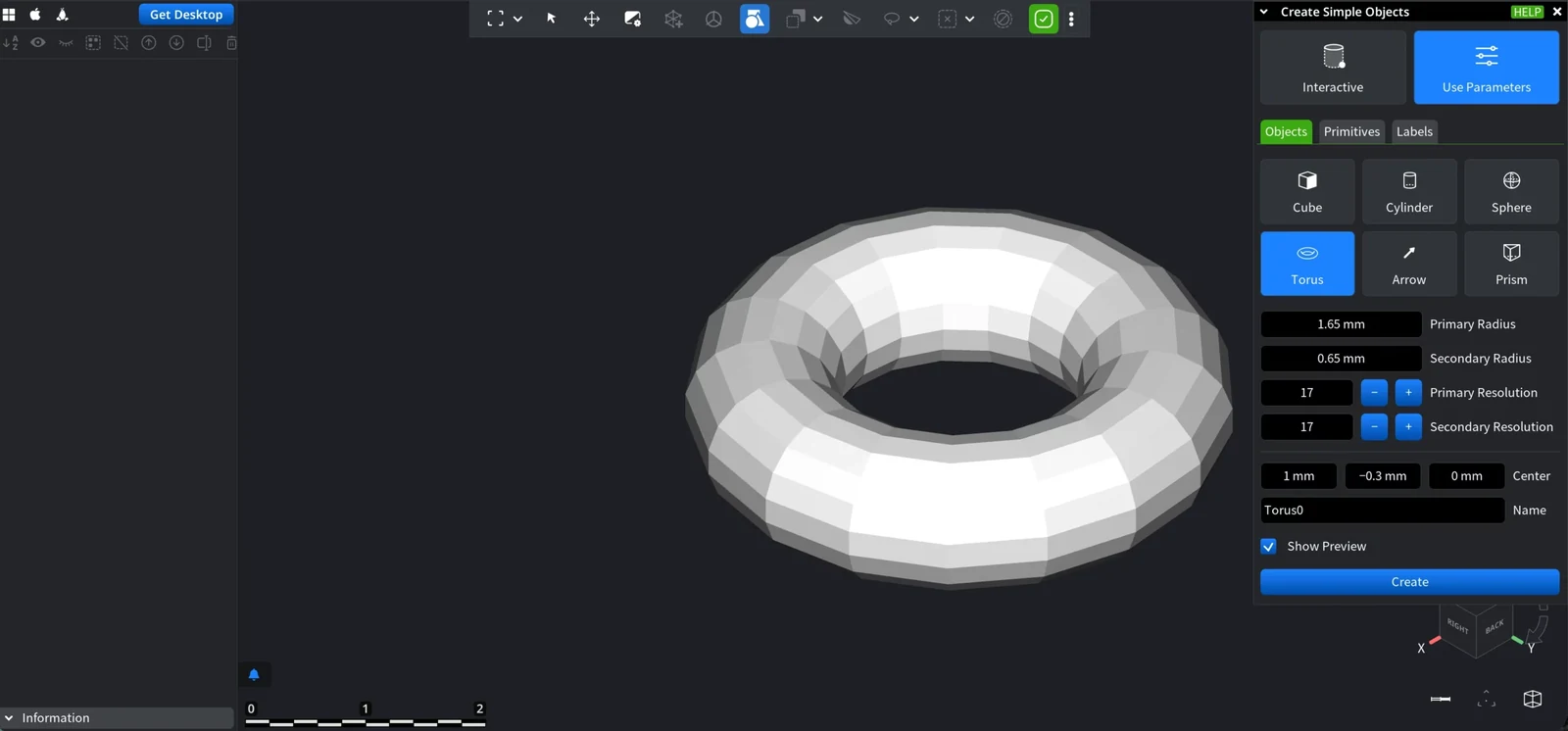
- Primary Radius is the distance from the center of the torus to the center of the tube.
- Secondary Radius is the radius of the tube.
- Primary Resolution and Secondary Resolution set the number of segments around the ring and around the tube.
Arrow
An arrow is a cylindrical shaft with a cone at the end.
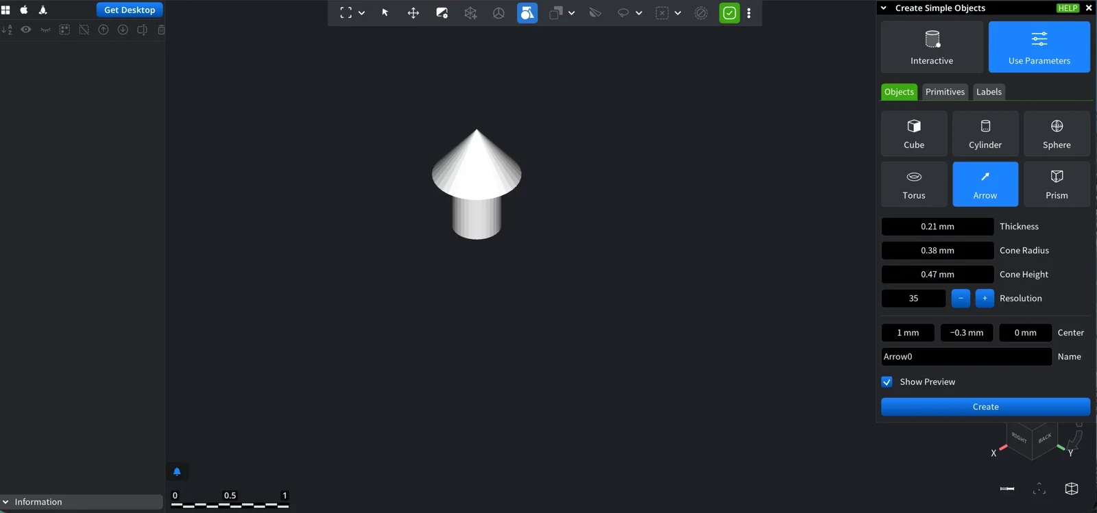
- Thickness is the diameter of the shaft.
- Cone Radius and Cone Height set the size of the tip.
- Resolution sets the number of segments around the circle.
Prism
A prism is a triangle extruded to a given height.
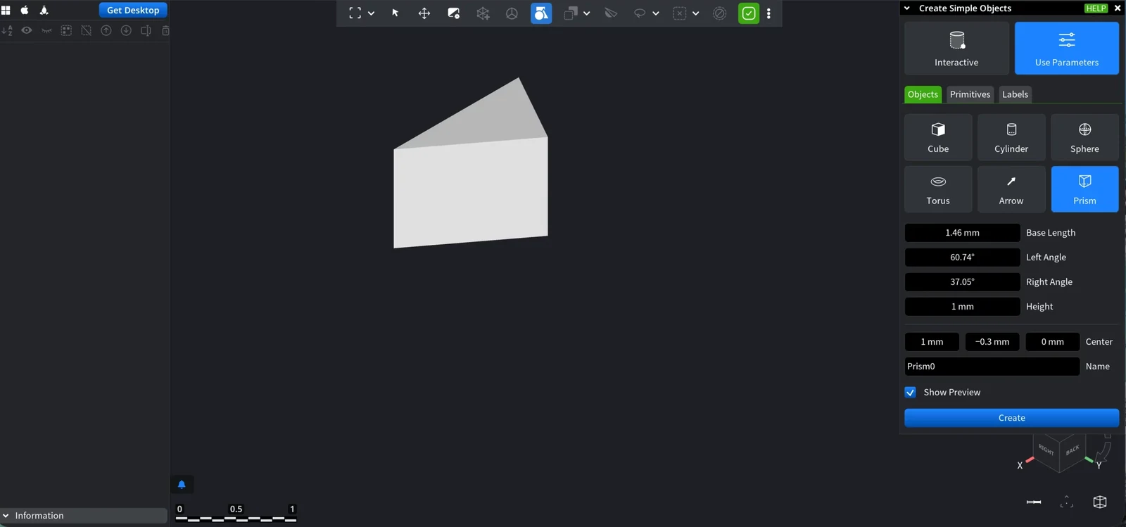
- Base Length is the length of the base edge of the triangle.
- Left Angle and Right Angle are the angles of the triangle at the two ends of the base edge.
- Height is the extrusion height of the prism.
Example: a cylinder to cut a hole
To drill a hole 30 mm in diameter through a wall of a part, make a cylinder that is longer than the wall is thick and place it on the wall:
- In Use Parameters, choose Cylinder.
- Set Diameter 0 and Diameter 1 to 30 mm and Length to 40 mm.
- Set Center to a point in the middle of the wall. Here it is x = 0 mm, y = −55 mm, z = 111.35 mm on the front wall of a housing.
- Turn on Show Preview, check that the cylinder crosses the wall, and click Create.
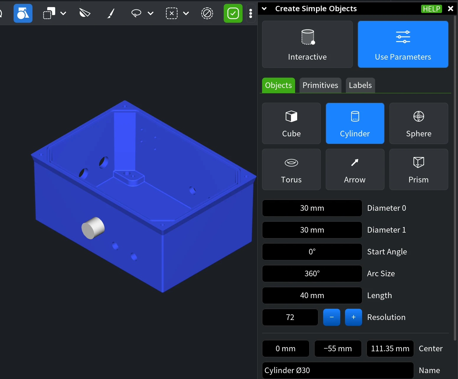
Then select the part and the cylinder and subtract the cylinder with Mesh Edit › Mesh Boolean (A - B). The whole example is in Boolean operations.
Primitives: points and segments
The Primitives tab creates exact points and line segments, for example to mark reference positions or to build a polyline.
Points
Enter the X, Y and Z coordinates and click Add. Every point appears in the list below with its number and coordinates. Select a point in the list to change it with Edit, duplicate it with Copy or remove it with Delete; Clear All removes all points.
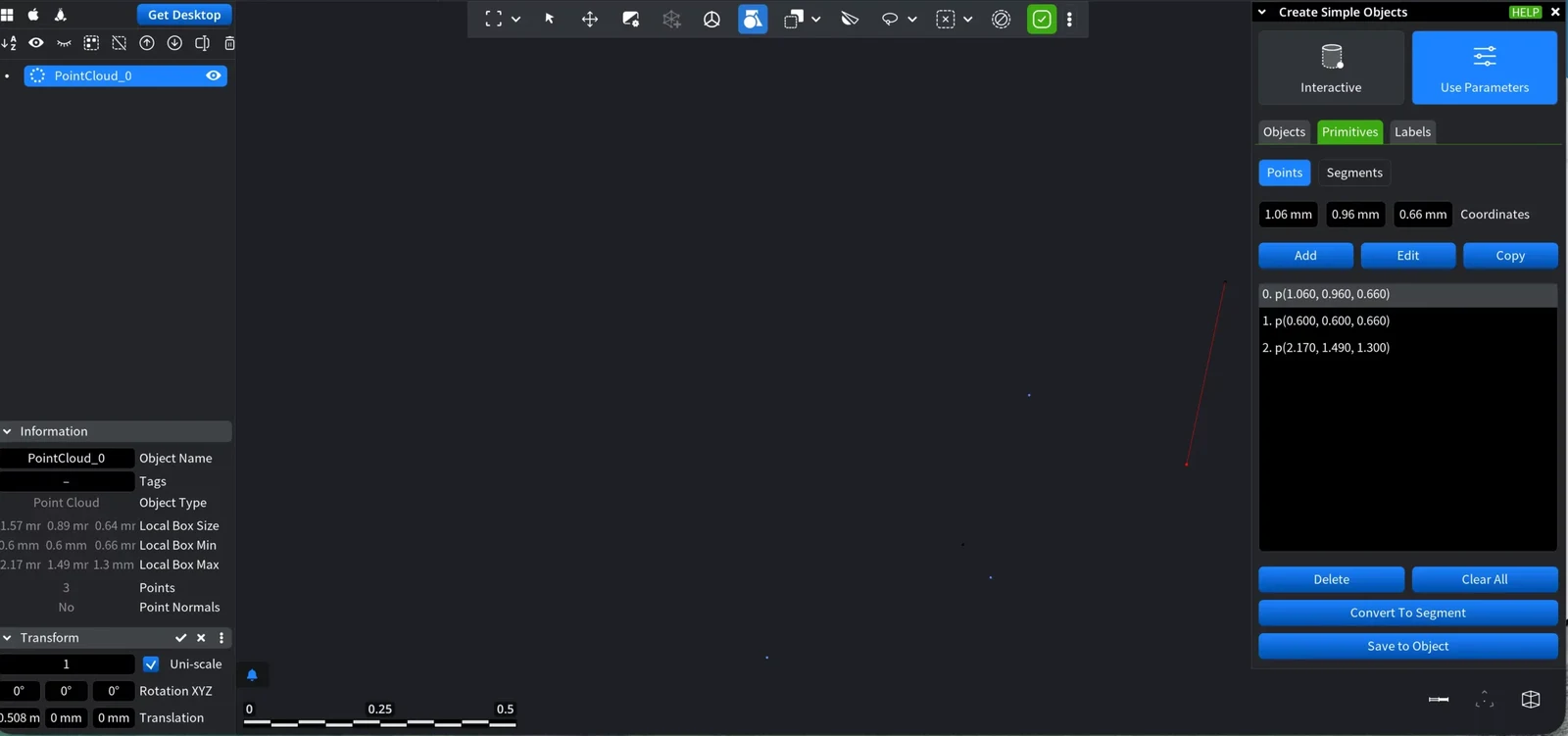
- Convert To Segment is available when the list has at least two points. Pick the first point (1) and the second point (2), then click Convert: the segment appears in the viewport and in the Segments list.
- Save to Object creates a point cloud object from all points in the list and adds it to the Scene tree.
Segments
A segment is set by its Origin and either a Destination point or a Direction vector: choose one in Set Method. Click Add to add the segment to the list; Edit, Copy, Delete and Clear All work as for points. Each segment in the list shows its origin (o) and its destination or direction (d).
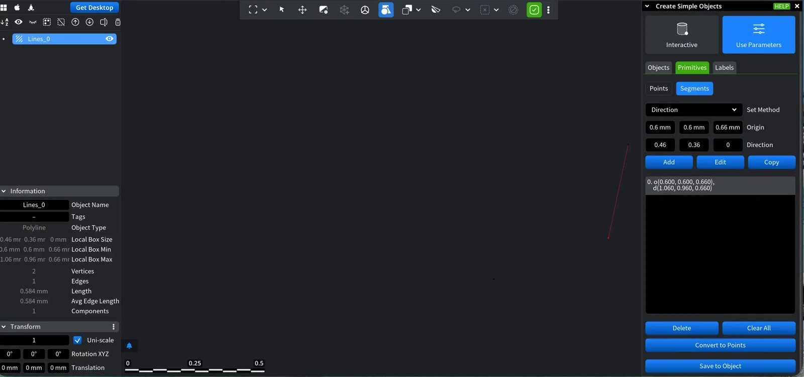
- Convert to Points turns the two ends of the selected segment into points in the Points list.
- Save to Object saves all segments of the list as one polyline object in the Scene tree.
Labels
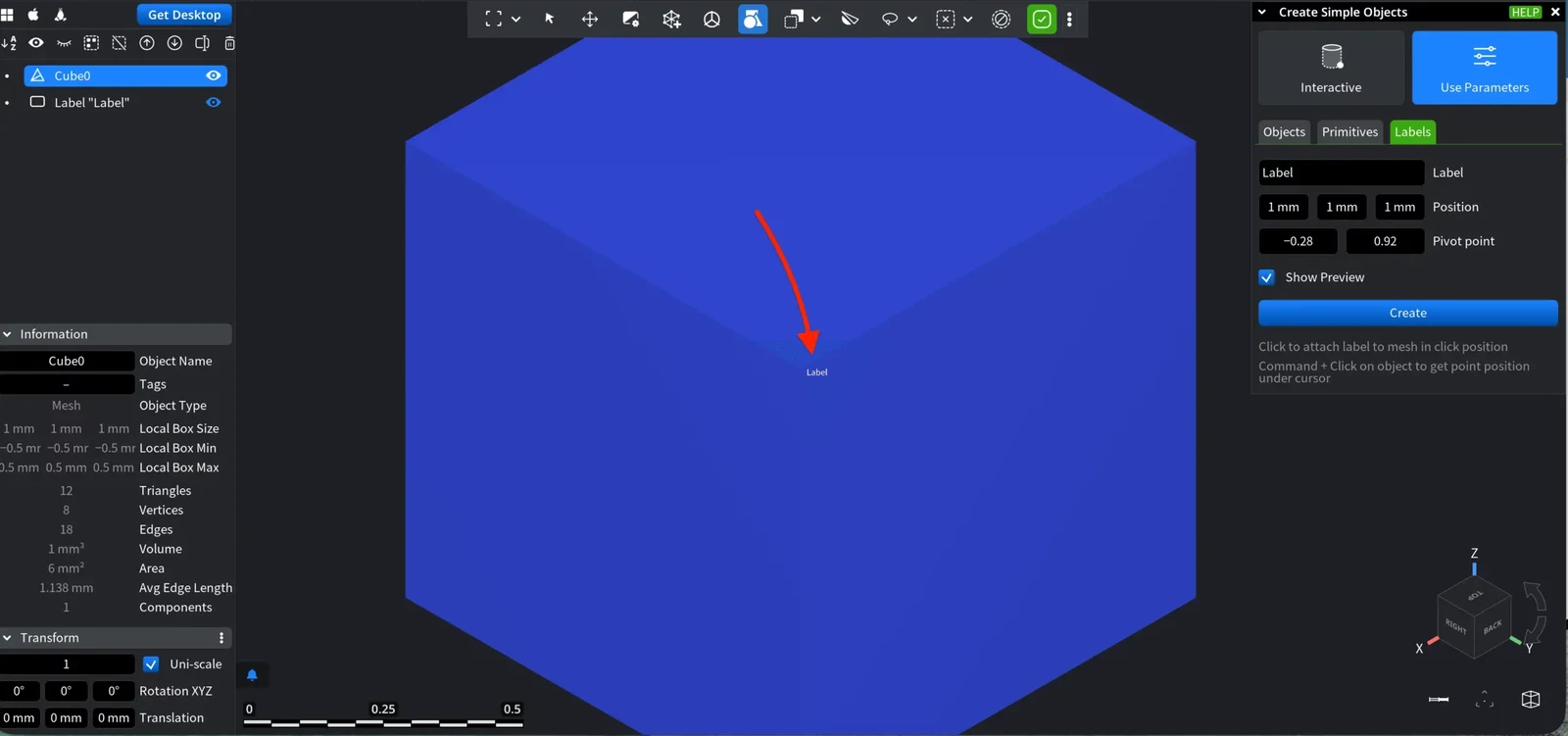
The Labels tab adds a text label to the scene, for example to mark a place on a model.
- Label is the text shown in the viewport.
- Position sets the 3D point of the label.
- Pivot point sets which point of the text is placed at Position.
- Show Preview shows the label before you click Create.
To create text as a 3D mesh, use Create Text instead.


