
Extrude Base makes a closed printable model with a flat base from an open or closed mesh, for example from an intraoral scan of a dental arch. It closes the holes of the mesh, extends the model down to a base opposite to the print direction, and can fill the undercuts, the areas that you cannot see when you look along the print direction.
You find it in Mesh Edit › Extrude Base. Select exactly one mesh first.
How to make a base
- Select one mesh in the Scene tree.
- Click Mesh Edit › Extrude Base. A red arrow appears on the model, and the Extrude Base panel opens.
- Point the arrow away from the future base, the way the model will stand: the base is built in the opposite direction. Click Direct to Camera to point the arrow at you, or Direct from Holes to let MeshInspector choose, or enter the three Direction values. You can also drag the arrow with the mouse.
- Optional: click Find Undercuts to select the undercuts for this direction, and Find Optimal Direction to turn the arrow so that there are fewer of them.
- Check the Options and click Extrude Base.
MeshInspector replaces the mesh of the object with the result and closes the panel. To get the original mesh back, use Undo; to keep it, make a copy with Clone first.
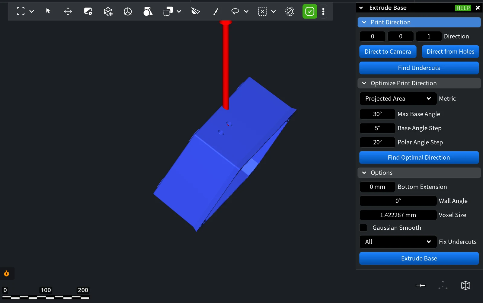
Print Direction
| Control | What it does |
|---|---|
| Direction | The three components (X, Y, Z) of the print direction, the direction of the arrow. When the panel opens it is 0, 0, 1. |
| Direct to Camera | Points the arrow toward you. Turn the view so that you look at the model from the top, then click it. |
| Direct from Holes | Points the arrow along the smallest side of a tight box around the model, away from its holes. |
| Find Undercuts | Selects the triangles that are hidden when you look from the tip of the arrow. |
Optimize Print Direction
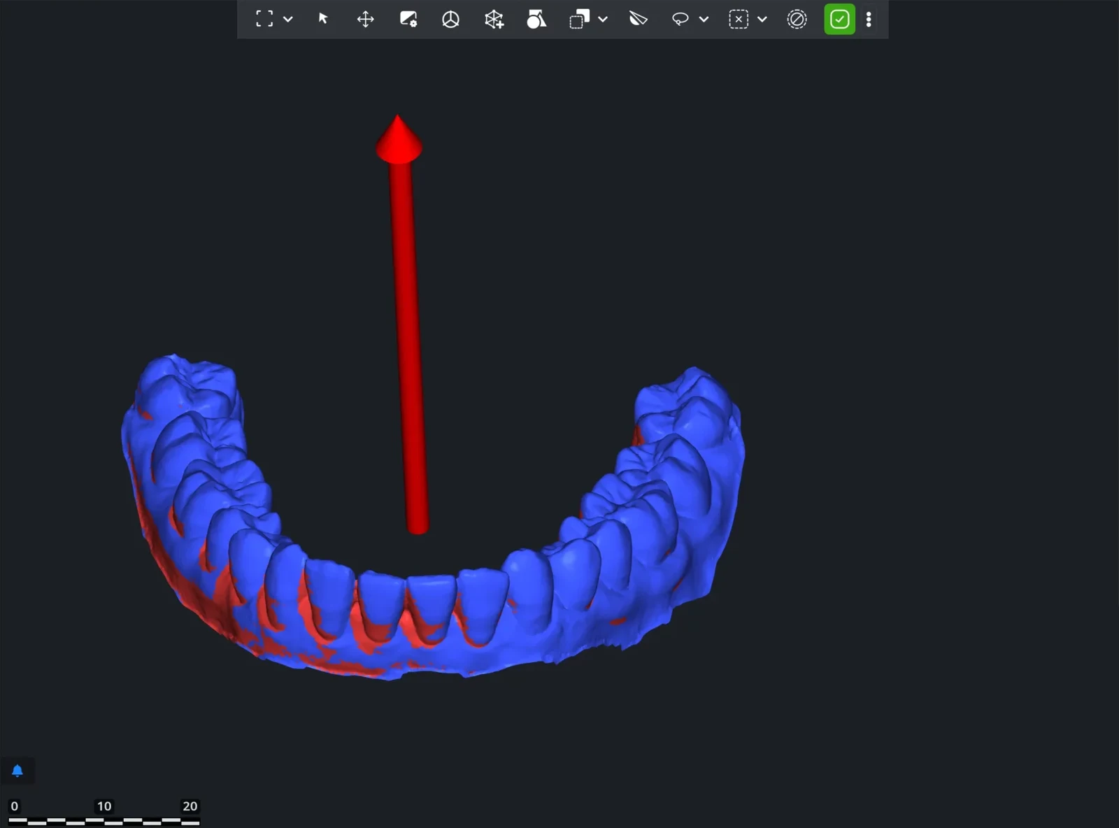
Find Optimal Direction tries directions around the current arrow and turns the arrow to the direction with the smallest undercuts. Set the arrow roughly first, for example with Direct to Camera.
| Setting | What it does | Default |
|---|---|---|
| Metric | What to minimize: Area is the total area of the undercut triangles; Projected Area is their area as you see it along the direction; Projected Area Approx is a faster approximation of Projected Area. | Projected Area |
| Max Base Angle | How far from the current arrow the candidate directions go | 30° |
| Base Angle Step | The step of the tilt from the current arrow | 5° |
| Polar Angle Step | The step around the current arrow | 20° |
Smaller steps check more directions and take longer.
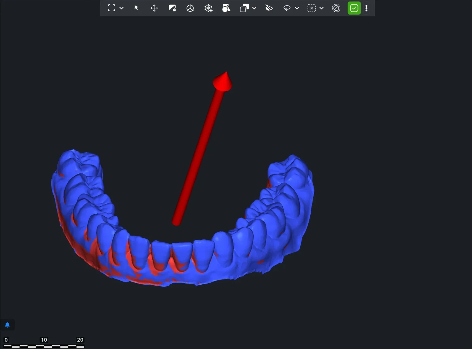
Before optimization, the arrow points in an arbitrary direction, and Find Undercuts marks many undercuts in red:
After Find Optimal Direction, the arrow points almost straight up, and fewer areas are undercuts:
Options
| Option | What it does | Default |
|---|---|---|
| Bottom Extension | The minimum length of the base below the model. With 0, the base is twice the Voxel Size long. | 0 mm |
| Wall Angle | The angle of the walls that fill the undercuts, from −60° to 60°. 0° makes vertical walls; a positive angle makes walls that widen downward; a negative angle makes walls that narrow downward. | 0° |
| Voxel Size | The resolution of the computation: the whole model is rebuilt with this precision. A smaller value keeps finer details but takes more time and memory. | Set from the model size |
| Gaussian Smooth | Smooths the result a little; useful if the model has thin walls | Off |
| Fix Undercuts | All fills all undercuts; Selection Only fills the undercuts only in the selected triangles, so that the other areas keep their shape. | All |
To fill the undercuts only in one area, select its triangles first, for example with Select › Select Boundary Tris for the edge of an open scan, then choose Selection Only.
Before Extrude Base, the dental arch is an open scan, and its undercuts are selected in red:
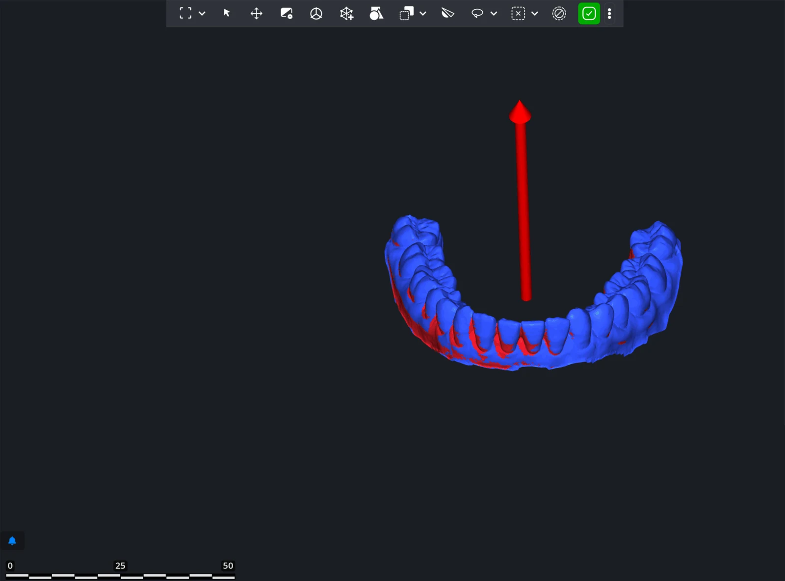
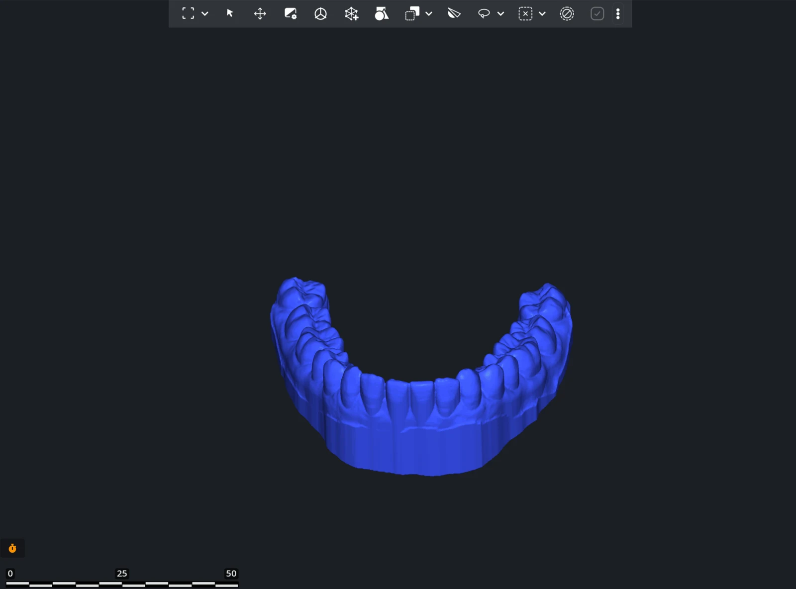
After Extrude Base, the model is closed and stands on a flat base:
What next
- Check the result with the Mesh Healer.
- To save material, hollow the model with Mesh Edit › Offset in Thickening mode and a negative Value: see Offset. Then you can fill the cavity with Lattice Structures.
- For the whole sequence on a dental scan, from trimming to lattice, see Preparing a dental model for 3D printing.

