

The Point and Line features mark a center and a direction on a mesh or a point cloud. Use a point for the center of a hole or of a region, and a line for an axis or the direction of an edge. Both are in the Create group of the Inspect tab and work like the other features (see How to Create and Measure Features).
What They Fit
| Feature | Result | Shows |
|---|---|---|
| Point | The average position of all input points | Its X, Y and Z coordinates next to the point |
| Line | The straight line that best follows the input points, drawn across the area they cover | The line in the viewport |
The input is the same as for every feature: picked points, the vertices of the selected area, the vertices of a hole boundary, or a part of another feature.
Create a Point or a Line
- In the Scene tree, select the mesh or point cloud.
- Go to Inspect › Create › Point (or Line).
- Choose the input:
- Pick Points: click points on the surface. Shift+click removes a point. For a Point, each new click replaces the previous one, so the point is simply where you clicked; to average many points, use Fit to Selection.
- Fit to Selection: select an area with Lasso, Rect, Polygon, Brush or Pick. If triangles are already selected, the feature is fitted to them at once.
- Fit to Mesh Boundary: click the boundary of a hole of the mesh (only when the mesh has holes).
- Pick Sub-feature: copy a part of a selected feature, for example the axis of a cylinder as a line or the center of a circle as a point.
- Click New Feature to keep the feature and make the next one, or close the panel.
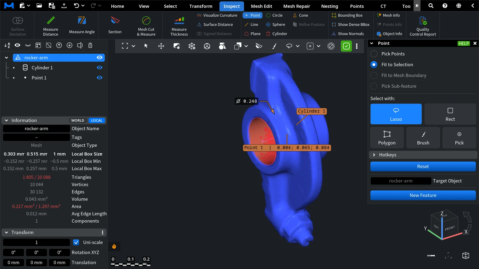
In the picture, the same selected hole wall gave Cylinder 1 and then Point 1. The point is the plain average of the selected vertices, so here it lies close to the axis of the cylinder; on a mesh with denser triangles on one side of the hole it moves toward that side.
Good to Know
- Center of a hole. A Point is the plain average of its points, so it is the center only when the points are spread evenly around the hole: points on one side, or denser triangles on one side, move it there. For an exact center, fit a Circle or a Cylinder to the hole and copy its center with Pick Sub-feature.
- Axis of a hole or a shaft. A Line follows the longest extent of its points, so on a short, wide hole it can lie across the hole. For a reliable axis, fit a Cylinder, select it, open Inspect › Create › Line and copy the axis with Pick Sub-feature.
- Refine. The Line panel has the Refine object section like the other features; the Point panel does not. To fit a point again later, select it and use Refine Feature.
Use Points and Lines
- Measure the distance from a point or a line to another feature with Measure Distance, or the angle between two lines with Measure Angle.
- Align a part with 3-2-1 Align: it can use a plane, a line and a point.


