The Extrude tool is used to extend selected areas of a mesh by pushing or pulling surface geometry outward or inward. It operates on selected surface triangles, generating new geometry that remains connected to the original surface. It is located under the Mesh Edit tab.
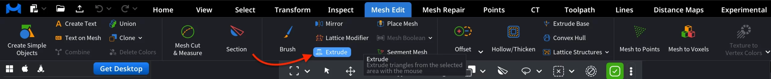
When Extrude is activated, a dedicated Extrude panel opens, and selection tools become available for defining the extrusion area.
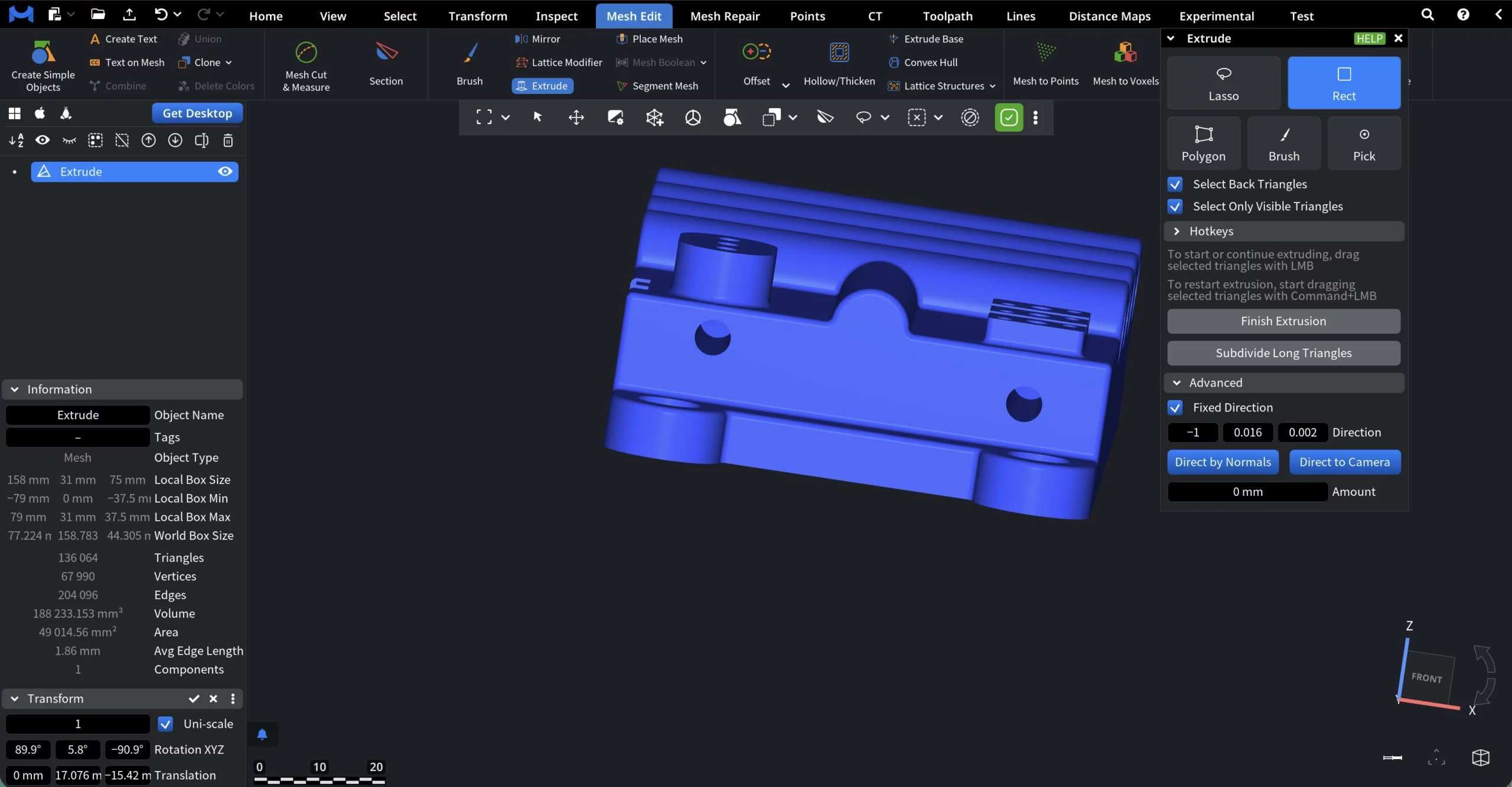
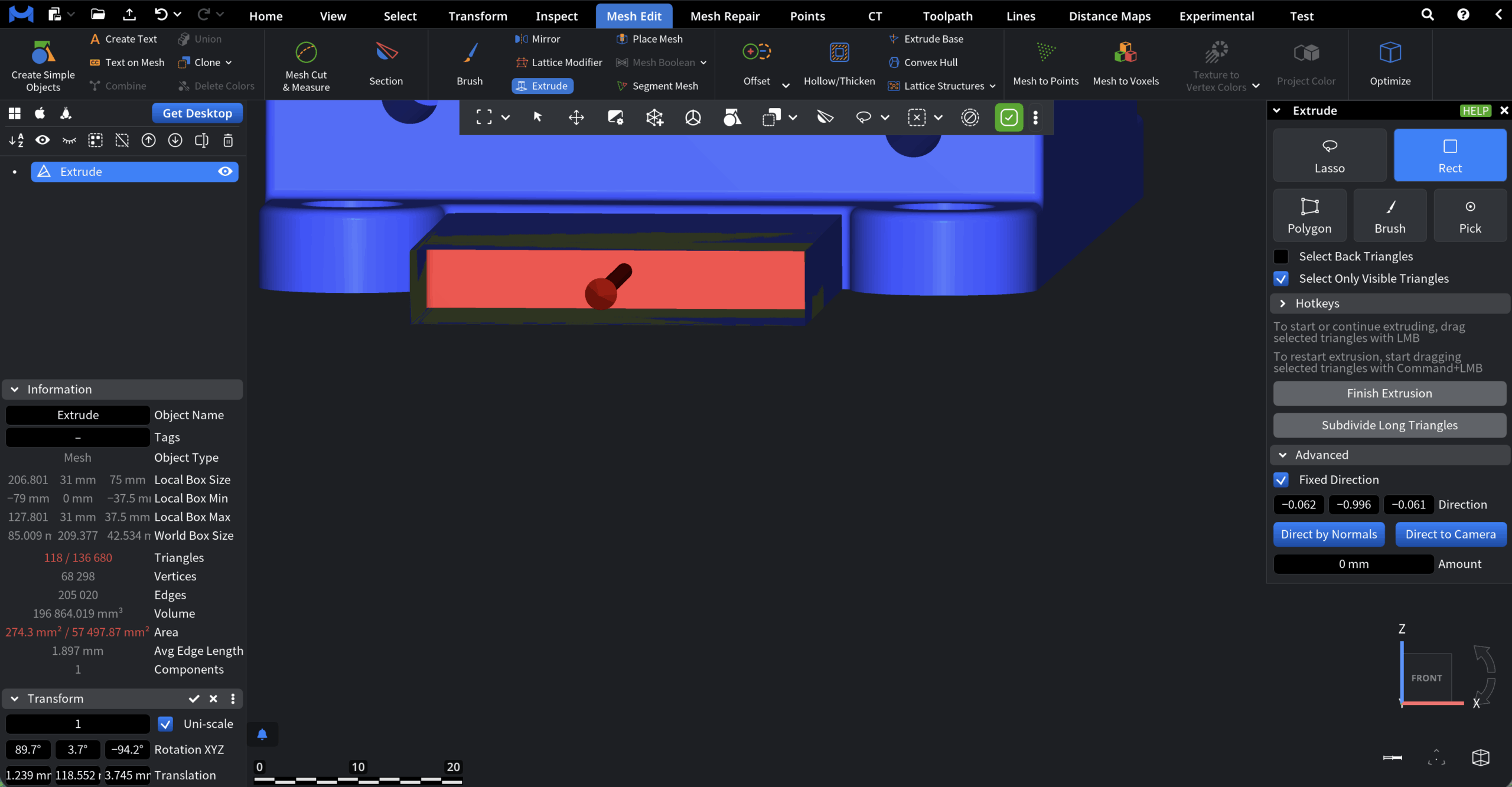
Selecting Geometry for Extruding
Extrude operates on selected triangles. You can define the selection using one of the following selection modes:
- Lasso selects triangles within a free-form shape drawn with the mouse.
- Rect selects triangles inside a rectangular area defined by a mouse drag.
- Polygon selects triangles inside a polygon defined by manually placed vertices.
- Brush selects triangles under a drawn brush stroke, allowing for more organic selections.
- Pick selects a single triangle with a mouse click.
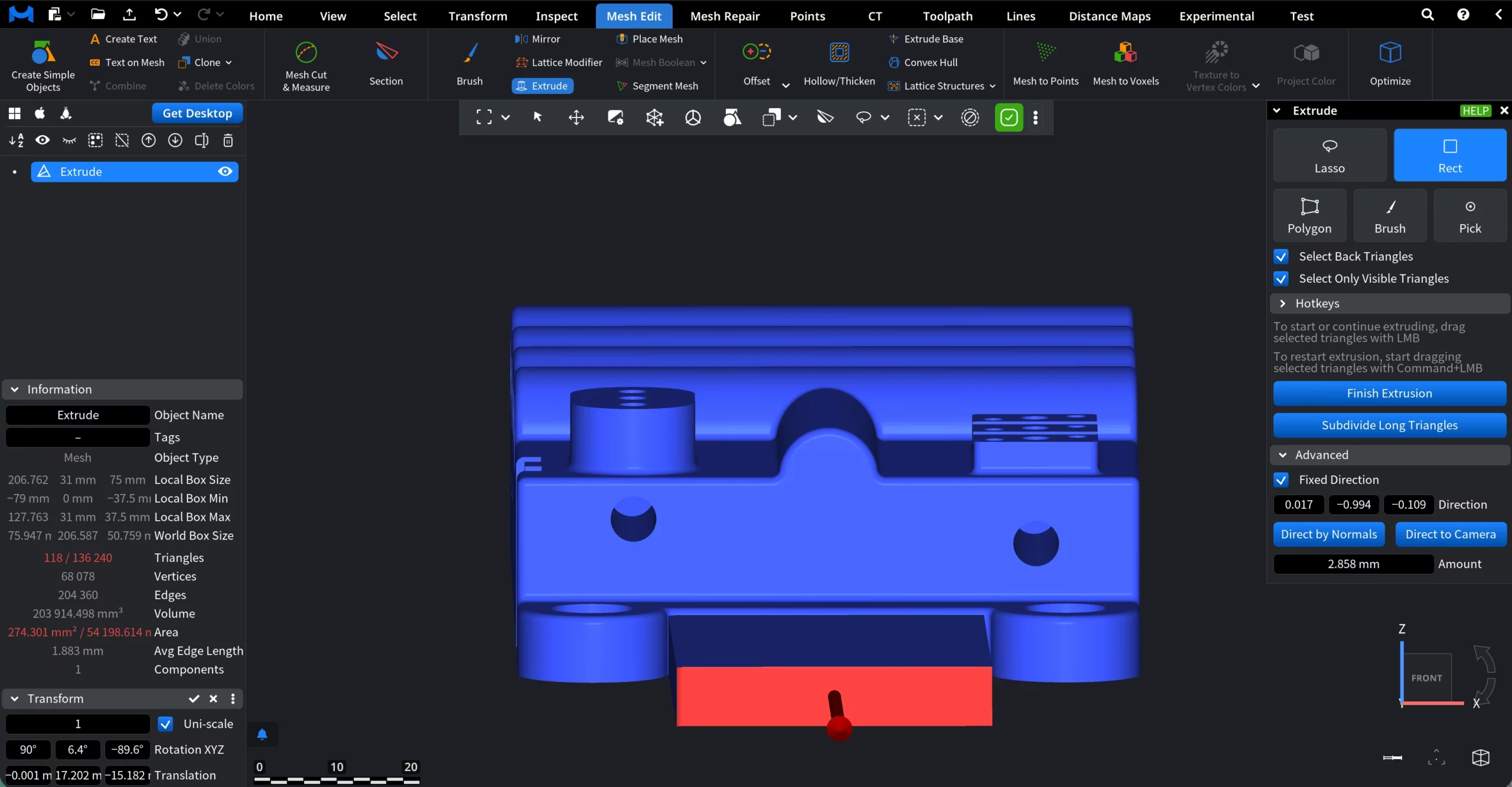
In this example, we will extrude the lower rectangular face by pushing it outward from the main body.
To select the region, we use the Rect selection mode. After defining the selection, we drag the selected triangles with LMB to extrude them outward.
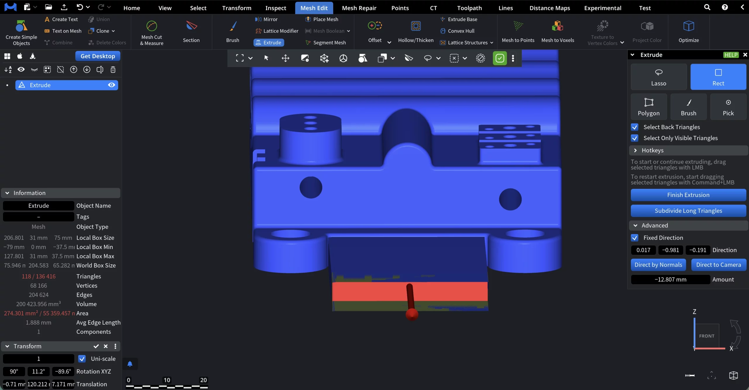
To restart extrusion from the newly generated surface, begin dragging the selected triangles with Command + LMB. In the example shown below, Extrude is restarted and applied inward.
Selection Options
- Select Back Triangles controls whether triangles oriented away from the camera are included in the selection.
- Select Only Visible Triangles limits the selection to triangles that are visible in the current view, excluding those occluded by other geometry.
Selection Hotkeys
The Hotkeys section defines how selections behave when modifier keys are held:
- None unselects the previous selection
- Command adds to the previous selection
- Shift unselects from the previous selection
- Shift + Command reverses the selection
- Command + A selects all primitives
Advanced Settings
The Advanced section controls how the extrusion direction and distance are defined.
- Fixed Direction. When it is enabled, extrusion is performed along a fixed vector. The direction is defined by three numeric components (X, Y, Z), representing the extrusion direction vector.
- Direction displays and allows manual editing of the three components of the extrusion direction vector. Changing these values adjusts the direction in which the selected triangles are extruded.
- Direct by Normals sets the extrusion direction based on the average normal of the selected triangles.
- Direct to Camera sets the extrusion direction toward the current camera position. As with Direct by Normals, applying this option finishes the current extrusion and updates the direction accordingly.
- Amount defines the extrusion distance along the specified direction. The value is displayed in scene units and updates the extrusion length. As such, this is an alternative to dragging with LMB when you need precise values.
Finalizing and Refining the Extrusion
Finish Extrusion finalizes the current extrusion operation and commits the generated geometry to the mesh. Once clicked, the extrusion is fixed, and the tool is ready for a new extrusion operation.
Subdivide Long Triangles subdivides the newly extruded geometry to prevent overly long or stretched triangles.
Here is how our example looks after we finalize the process.
The Extrude tool provides a flexible way to add new geometry while maintaining continuity with the original mesh. By combining precise selection controls with configurable direction and distance settings, MeshInspector's Extrude supports quick, controlled, and production-ready mesh modifications.