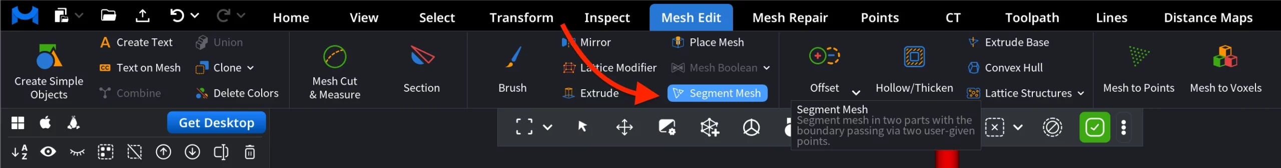
The Segment Mesh tool splits a mesh into two parts by defining a boundary that passes through at least two user-defined points. The tool is located under the Mesh Edit tab.
The segmentation boundary propagates across the surface and adapts to the mesh curvature. This makes it especially effective for isolating protruding features, where the boundary follows natural bulges and surface relief instead of slicing straight through the model.
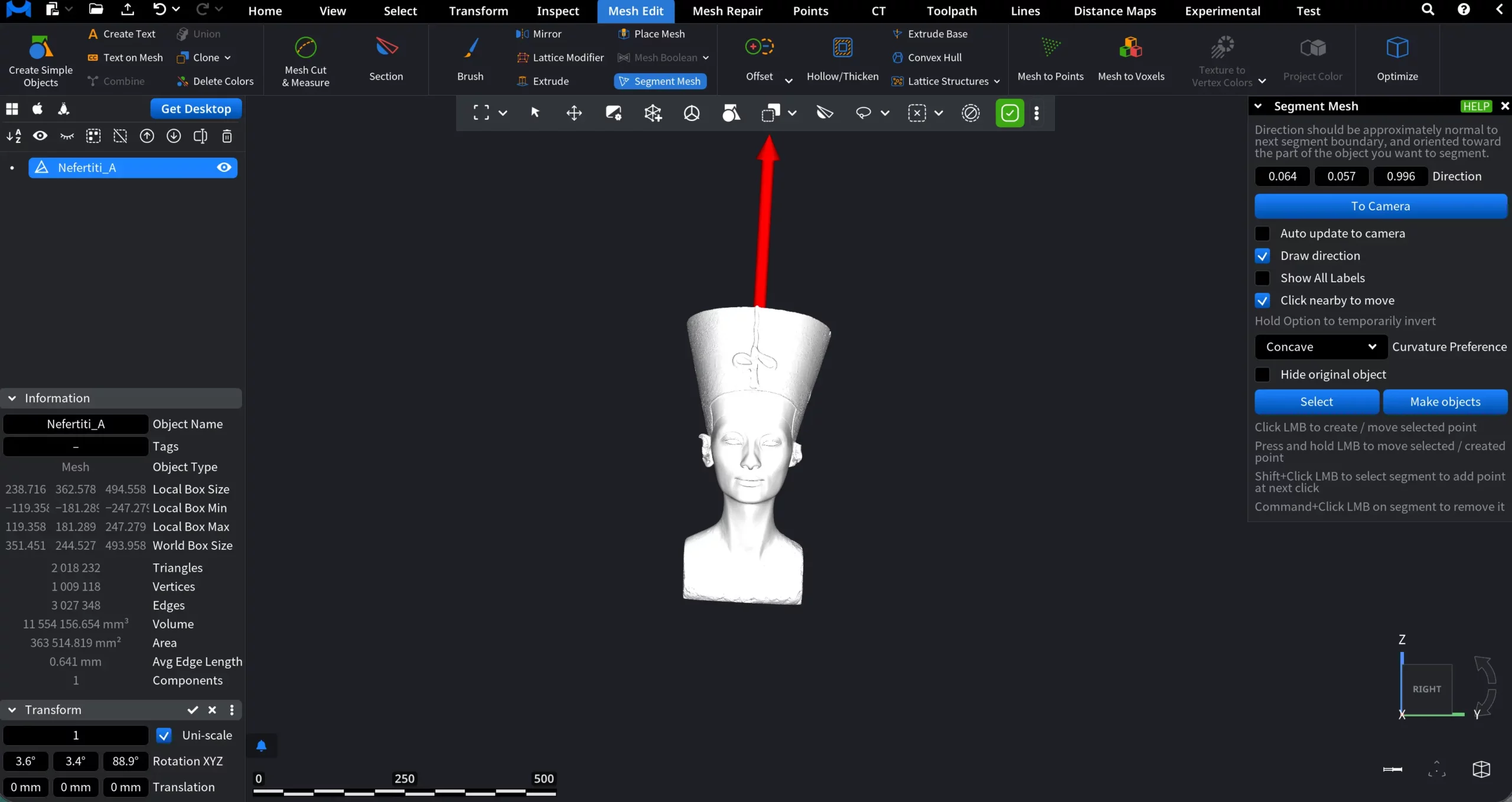
When the tool is activated, a dedicated Segment Mesh panel opens, and its controls become available.
Segmentation Settings
Segmentation is guided by a direction vector, shown above, which determines how the boundary propagates across the mesh surface. The direction should be approximately normal to the intended segment boundary and oriented toward the part of the object you want to segment.
- Direction (X, Y, Z) defines the components of the direction vector numerically.
- To Camera aligns the direction vector toward the current camera position.
- Auto update to camera. When enabled, it updates the direction vector automatically to viewer as the camera moves.
- Draw direction displays the direction vector in the viewport as a red arrow for visual verification.
- Show All Labels displays labels for all segmentation points and segments.
- Click nearby to move allows moving points by clicking near them instead of directly on the point.
- Curvature Preference controls how the segmentation boundary reacts to surface curvature during propagation. The available modes, i.e., Concave, Convex, and Geodesic, influence whether the boundary favors certain curvature characteristics or follows the shortest surface path.
How to Interact with Segmentation
- Click LMB to create or move a selected point.
- Press and hold LMB to reposition the selected or newly created point.
- Shift + Click LMB on a segment to add a new point at the next click.
- Command + Click LMB on a segment to remove it.
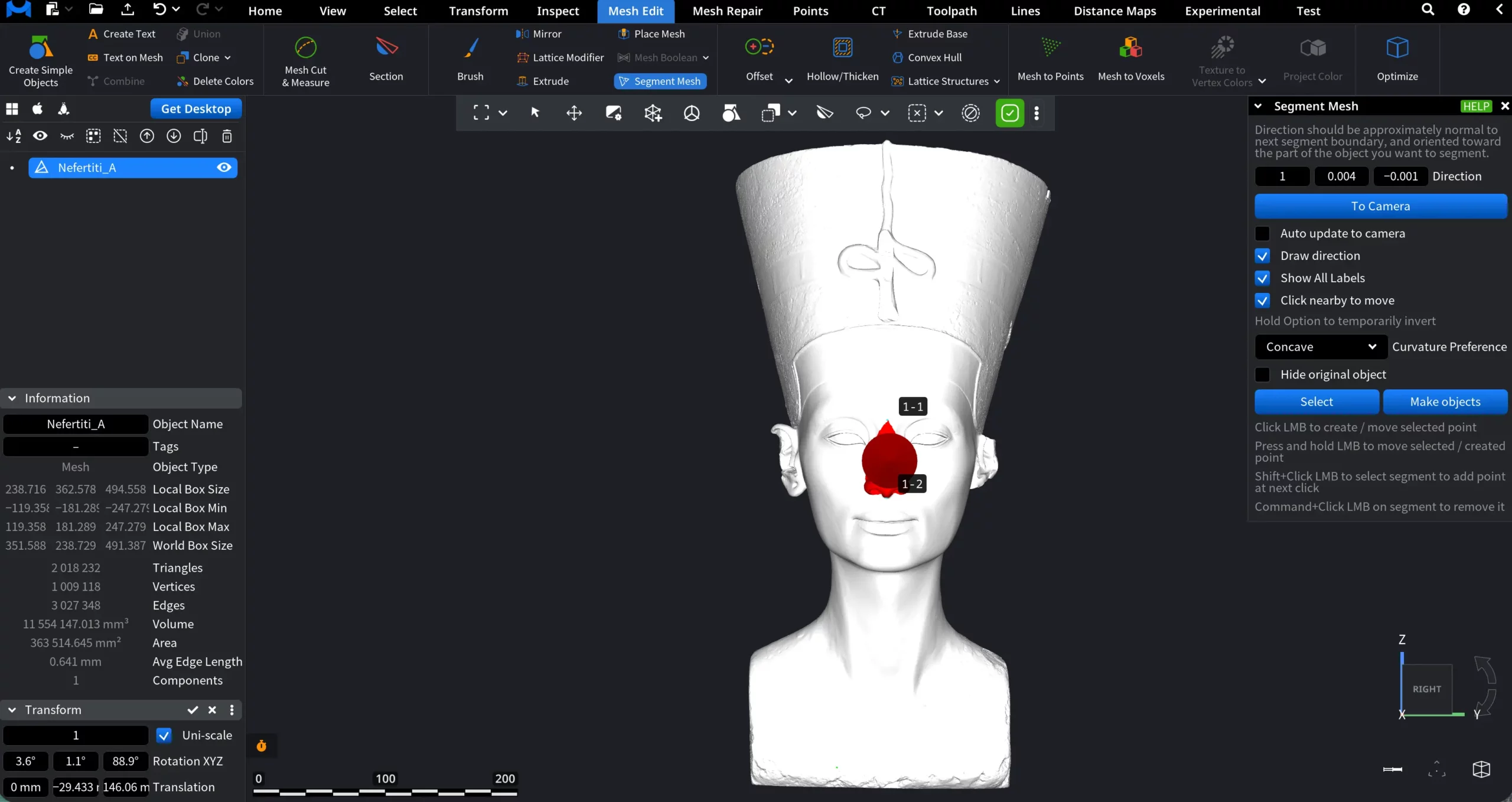
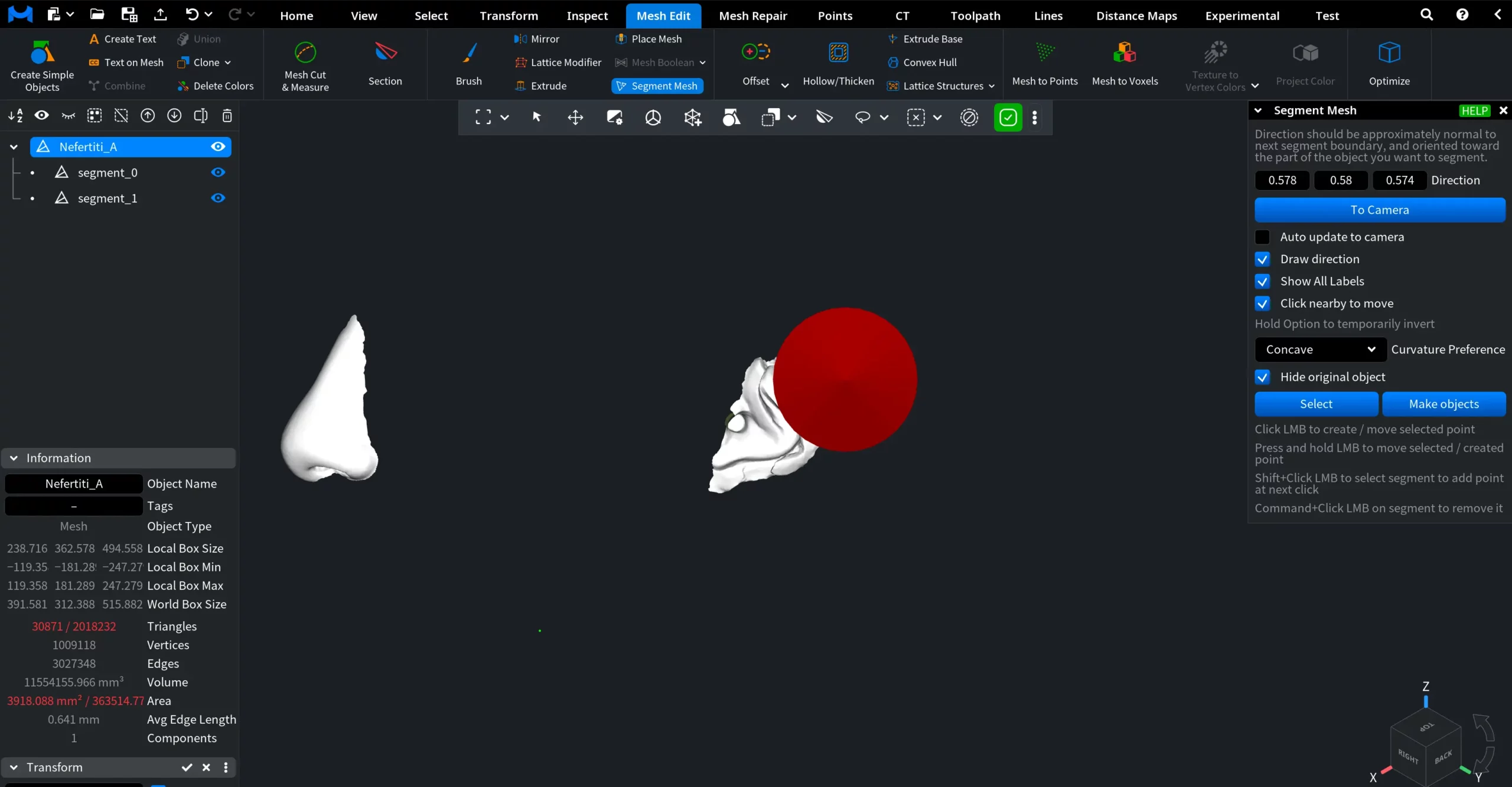
In the screenshot below, showing a Nefertiti mesh, we show how to segment it, focusing on the nose. First, we:
- Clicked To Camera to align the direction vector with the current view.
- Created two points (1-1 and 1-2) with the left mouse button to define the boundary around the nose.
- Since the nose represents a distinct surface feature, Curvature Preference was set to Concave to guide how the boundary wraps around the region.
Output Options
- Select converts the resulting segments into a face selection.
- Make objects creates separate mesh objects from the segmented parts.
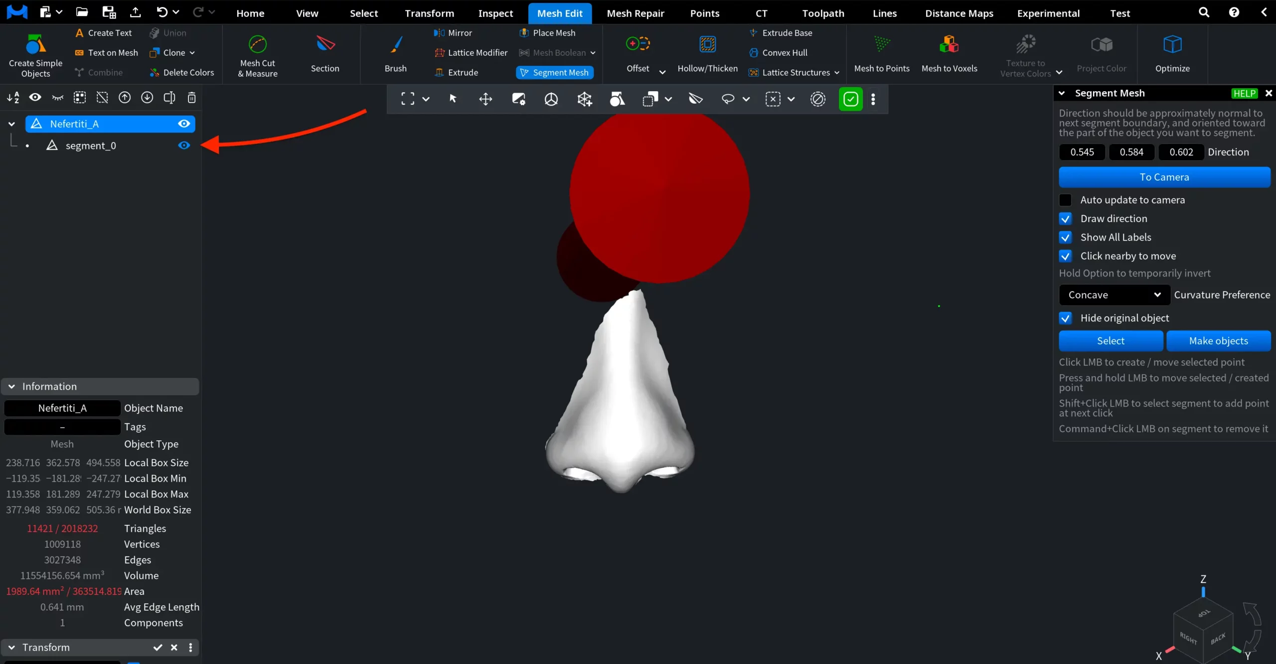
- Hide original object. When enabled, it hides the original mesh after segmentation, leaving only the generated segments visible.
In our example, we defined the zone of interest, chose Hide original object, then clicked Select and Make objects. The nose was created as a separate mesh object.
You can create as many segments as you need. In the screenshot below, having followed the same route, we created two objects, isolating both the nose and one ear (in this case, points were denoted as 1-1, 1-2, 2-1, 2-2).
All in all, the Segment Mesh tool provides a controlled and curvature-aware way to divide a mesh into meaningful parts. By combining direction control and curvature preference, you can isolate protruding or complex surface regions with precision.