MeshInspector allows users to create six types of geometric primitive mesh objects in the scene: cubes, cylinders, spheres, toruses, arrows, and prisms. To start creating them, go to the Mesh Edit tab and click Create Simple Objects.

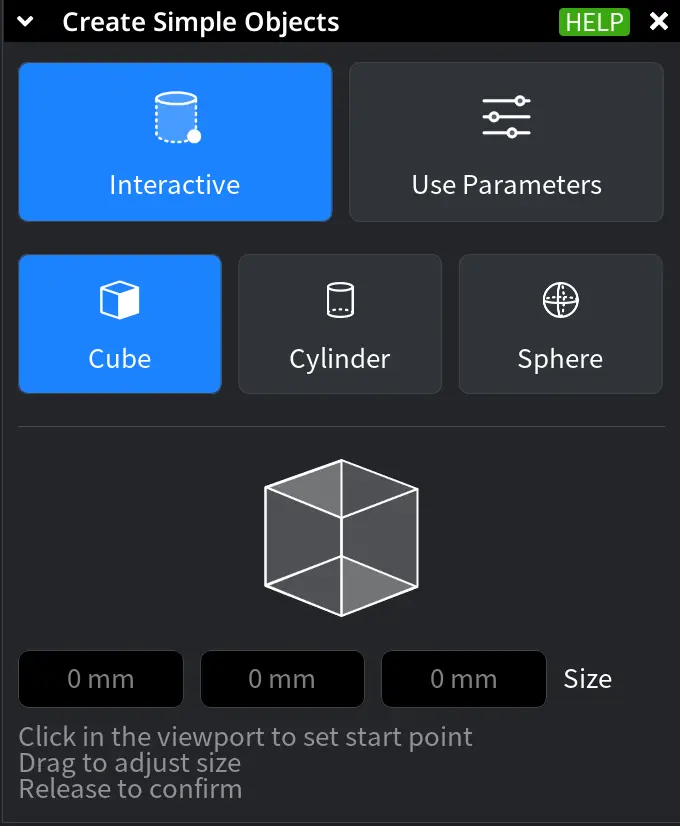
Clicking it opens the dedicated Create Simple Objects tab. There, two approaches to mesh creation are available:
- Interactive
- Use Parameters
Interactive
The Interactive mode lets you create Simple Objects directly in the viewport. You define the Simple Object’s size, orientation, and position visually by placing and adjusting it in the scene using the mouse, as shown below.
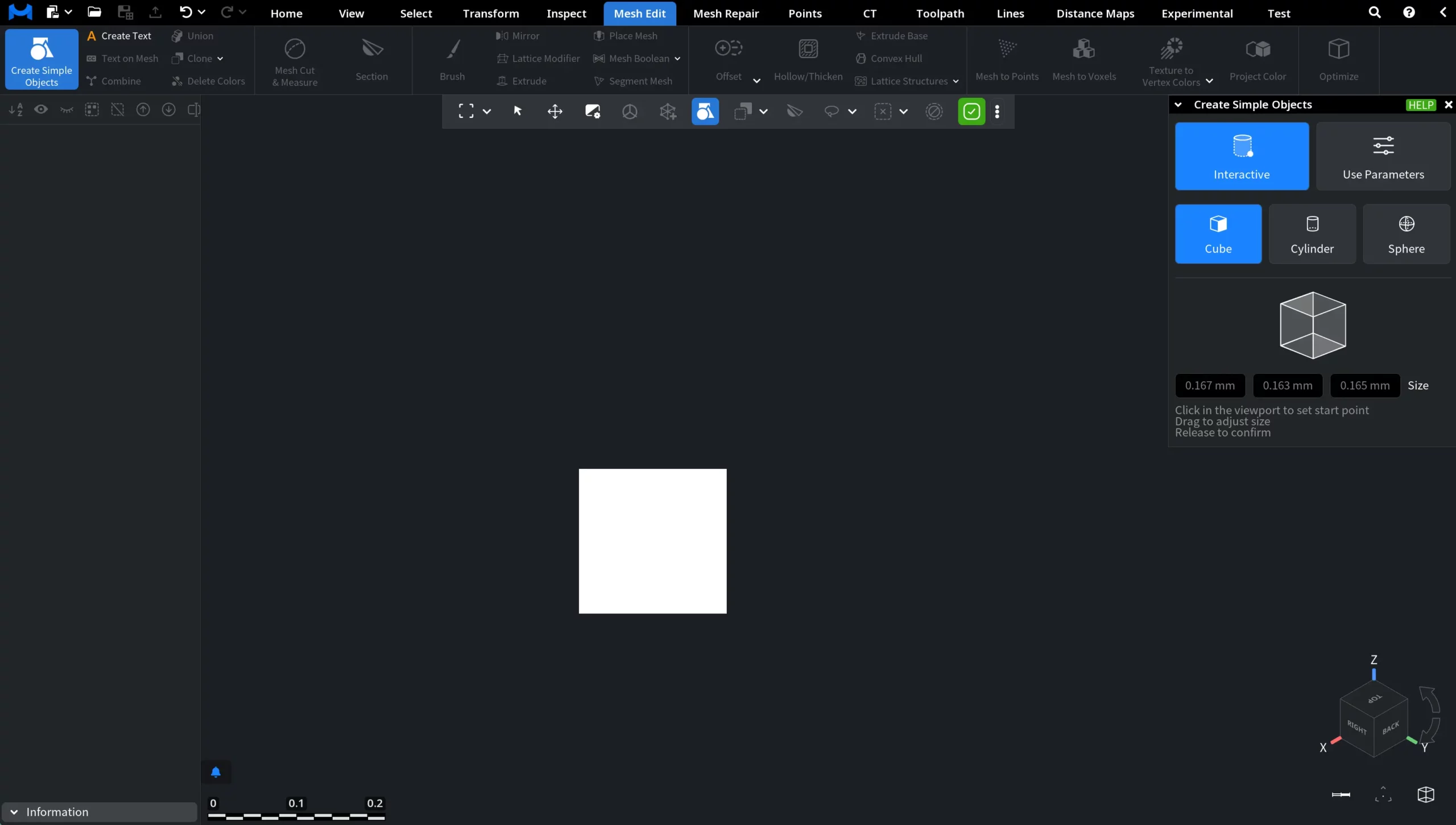
Release to finalize the process and add the mesh to the scene and its tree (the Simple Object will become blue, not a white preview, once you do so).
With this tool, three types of mesh objects can be created, with their corresponding dimensions displayed in the tab:
- Cube (size along X, Y, and Z axes)
- Cylinder (diameter and length)
- Sphere (radius)
Use Parameters
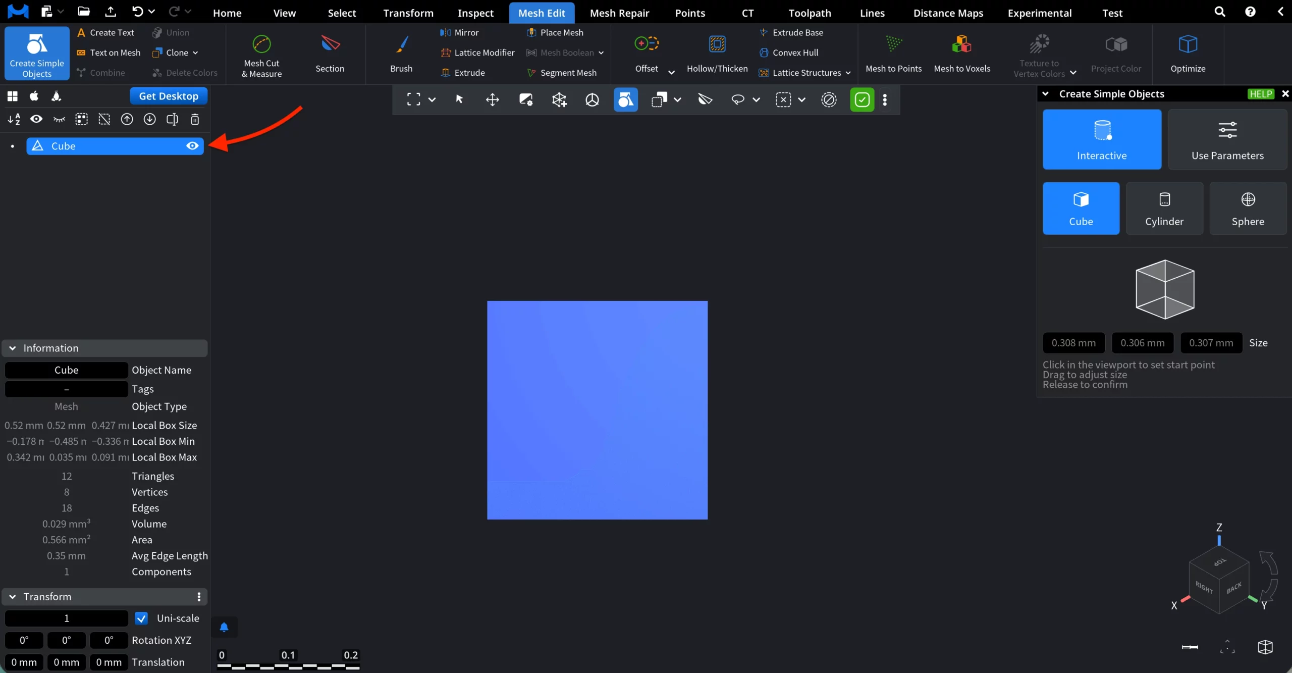
The Use Parameters option provides greater control, but is slower in practice than the Interactive mode. Here, the following Simple Objects are available: Cube (which can also be turned into a Parallelepiped), Cylinder, Sphere, Torus, Arrow, and Prism. Also, you can create Primitives and Labels.
Objects
1. Cube
When Cube is selected in Use Parameters mode, the object is created using explicit numeric values.
To create a cube, configure the following parameters:
- Size defines the Cube dimensions. By default, the same value is applied to all edges, but you can change each one by entering a value manually or by dragging the slider.
- Center sets the position of the Cube's center in the scene.
- Name assigns a name to the created Cube.
When Show Preview is enabled, a temporary preview of the Cube is displayed in the viewport before creation. Once you are satisfied with the result, click Create to finalize the process.
1.2 Parallelepiped
Enable Parallelepiped in the Cube tab to create a rectangular solid with independently defined edge lengths. When this option is turned on, the Size parameter is replaced by individual Edge controls.
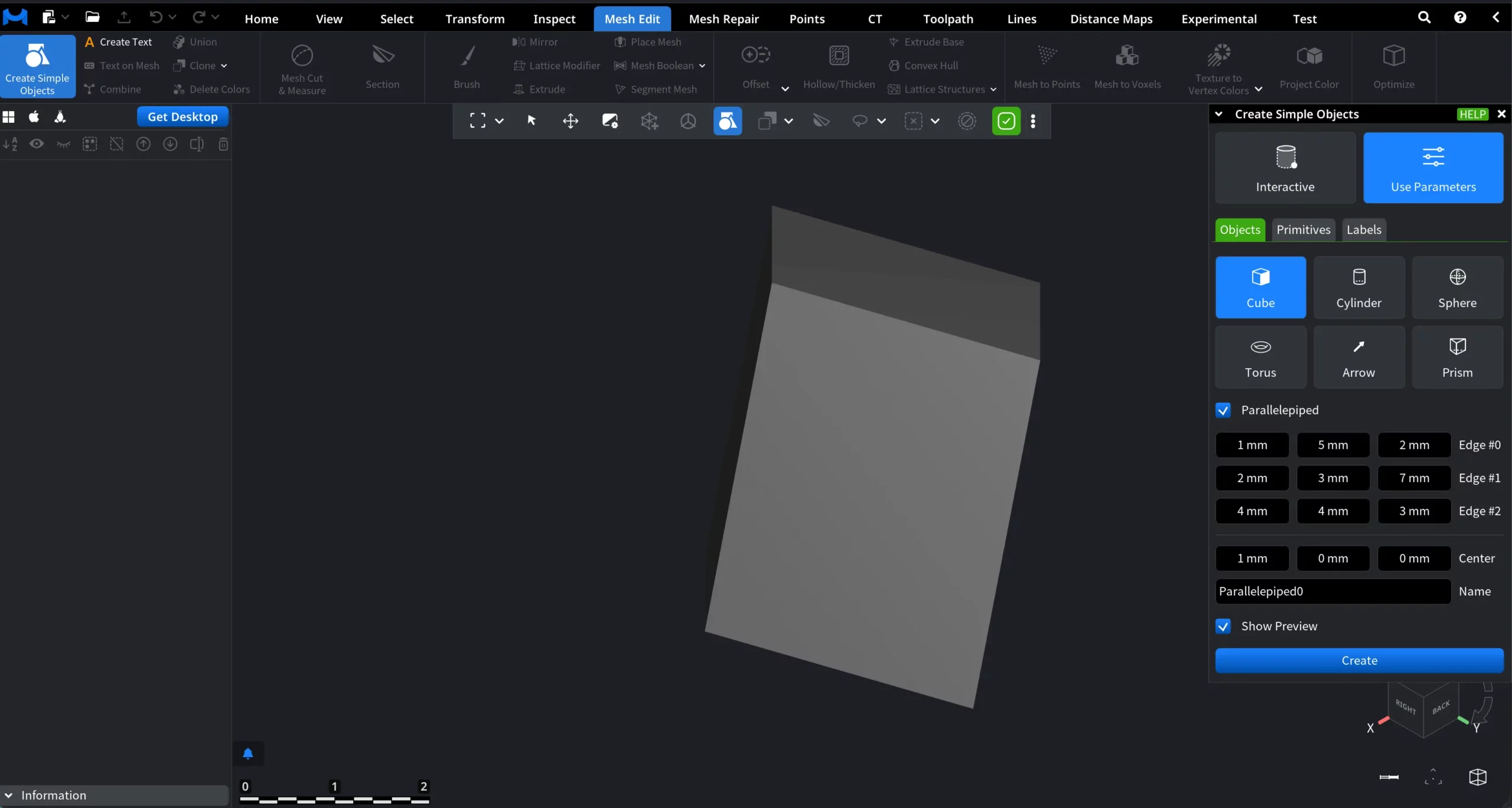
Configure the following parameters:
- Edge #0 defines the length of the first edge.
- Edge #1 defines the length of the second edge.
- Edge #2 defines the length of the third edge.
2. Cylinder
The Cylinder is defined by its base diameter and length, forming a closed cylindrical surface.
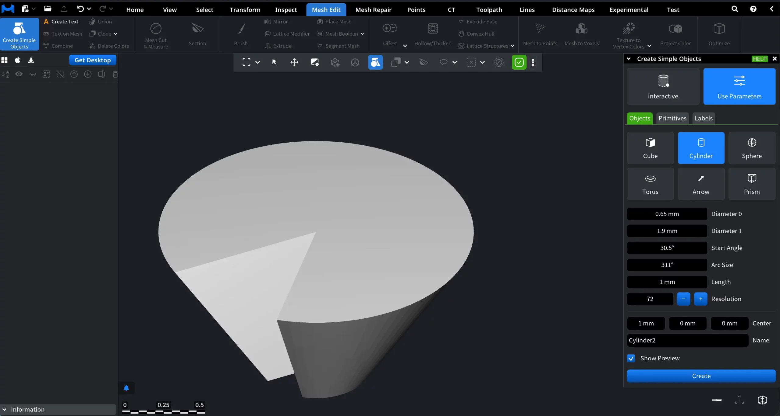
To create a Cylinder, configure the following parameters:
- Diameter 0 defines the diameter of one base of the Cylinder.
- Diameter 1 defines the diameter of the opposite base. If Diameter 0 and Diameter 1 are equal, a regular Cylinder is created. If the values differ, a conical shape is created.
- Start Angle defines the starting angle of the cylindrical segment.
- Arc Size defines the angular span of the Cylinder. A value of 360° creates a closed Cylinder. Smaller values create an open cylindrical segment.
- Length defines the height of the Cylinder along its axis.
- Resolution controls the number of segments used to approximate the circular shape. Higher values result in smoother geometry.
- Center sets the position of the Cylinder's center in the scene.
- Name assigns a name to the Cylinder.
When Show Preview is enabled, a temporary preview of the Cylinder is displayed in the viewport.
Once the result is satisfactory, click Create to finalize the object and add it to the scene. Also, Create Feature Object can be used with certain Cylinder parameters.
3. Sphere
The Sphere is defined by its radius and mesh resolution, forming a closed spherical surface.
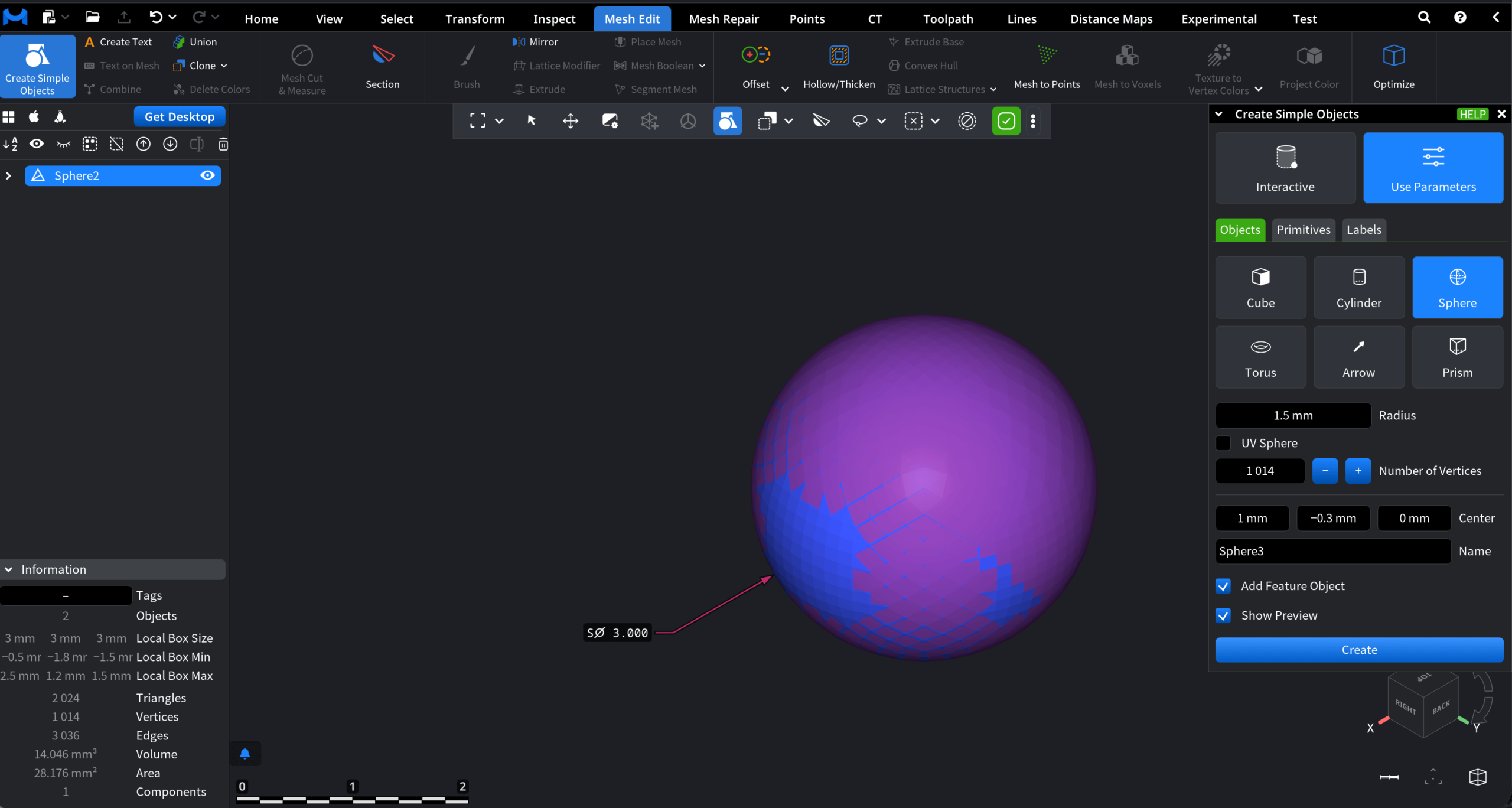
To create a Sphere, configure the following parameters:
- Radius defines the sphere radius. The on-screen indicator shows the radius value while adjusting it in the viewport.
- UV Sphere, when enabled, creates a UV-mapped sphere with separate horizontal and vertical resolution controls.
-
Horizontal Resolution controls the number of segments around the Sphere. Vertical Resolution controls the number of segments from top to bottom.
-
When UV Sphere is disabled, the Sphere resolution is defined by Number of Vertices, which sets the overall mesh density.
- Center sets the position of the Sphere’s center in the scene.
- Name assigns a name to the created Sphere.
- Show Preview displays a temporary preview of the Sphere in the viewport before creation.
Once you are satisfied with the outcomes, click Create to finalize the process. On top of that, you can also enable Add Feature Object, as shown in the screenshot above.
4. Torus
The Torus is defined by its main radius and tube radius, forming a ring-shaped geometry.
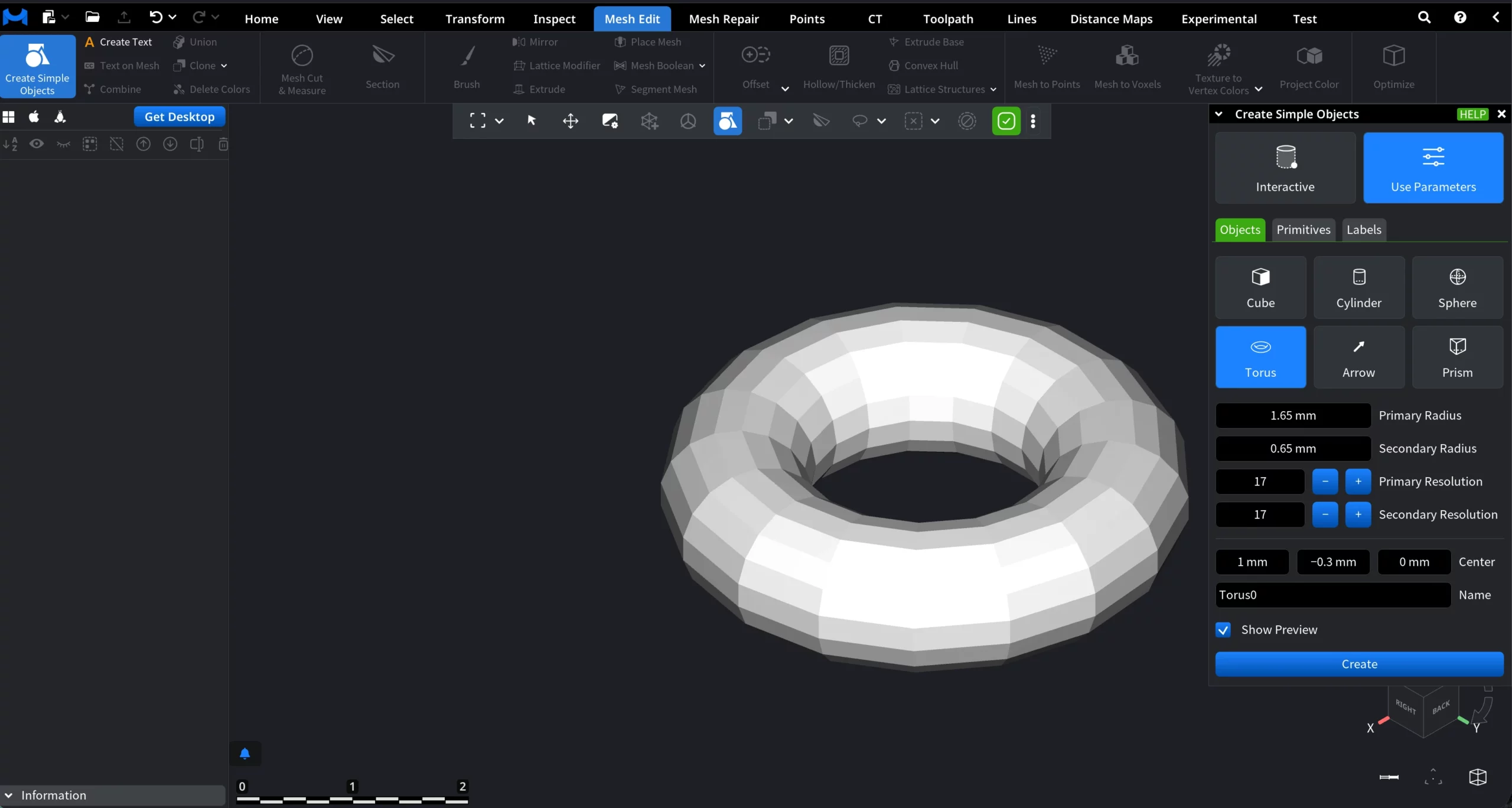
To create a Torus, configure the following parameters:
- Primary Radius defines the main radius of the Torus, i.e., the distance from the center of the torus to the center of the tube.
- Secondary Radius defines the radius of the tube itself.
- Primary Resolution controls the number of segments around the main circular path of the Torus.
- Secondary Resolution controls the number of segments around the tube cross-section.
- Center sets the position of the Torus center in the scene.
- Name assigns a name to the created Torus.
Show Preview displays a temporary preview of the Torus in the viewport before creation.
Once you are satisfied with the result, click Create to finalize the process.
5. Arrow
The Arrow consists of a cylindrical shaft and a conical tip.
![]()
To create an Arrow, configure the following parameters:
- Thickness defines the diameter of the cylindrical shaft.
- Cone Radius sets the base radius of the conical tip.
- Cone Height controls the length of the conical tip.
- Resolution defines the number of segments used to approximate the circular geometry. Higher values produce smoother results.
- Center sets the position of the arrow’s center in the scene.
- Name assigns a name to the created Arrow.
Show Preview displays a temporary preview of the Arrow in the viewport before creation.
Once you are satisfied with the result, click Create to finalize the process.
6. Prism
A Prism is defined by its base shape and extrusion height.
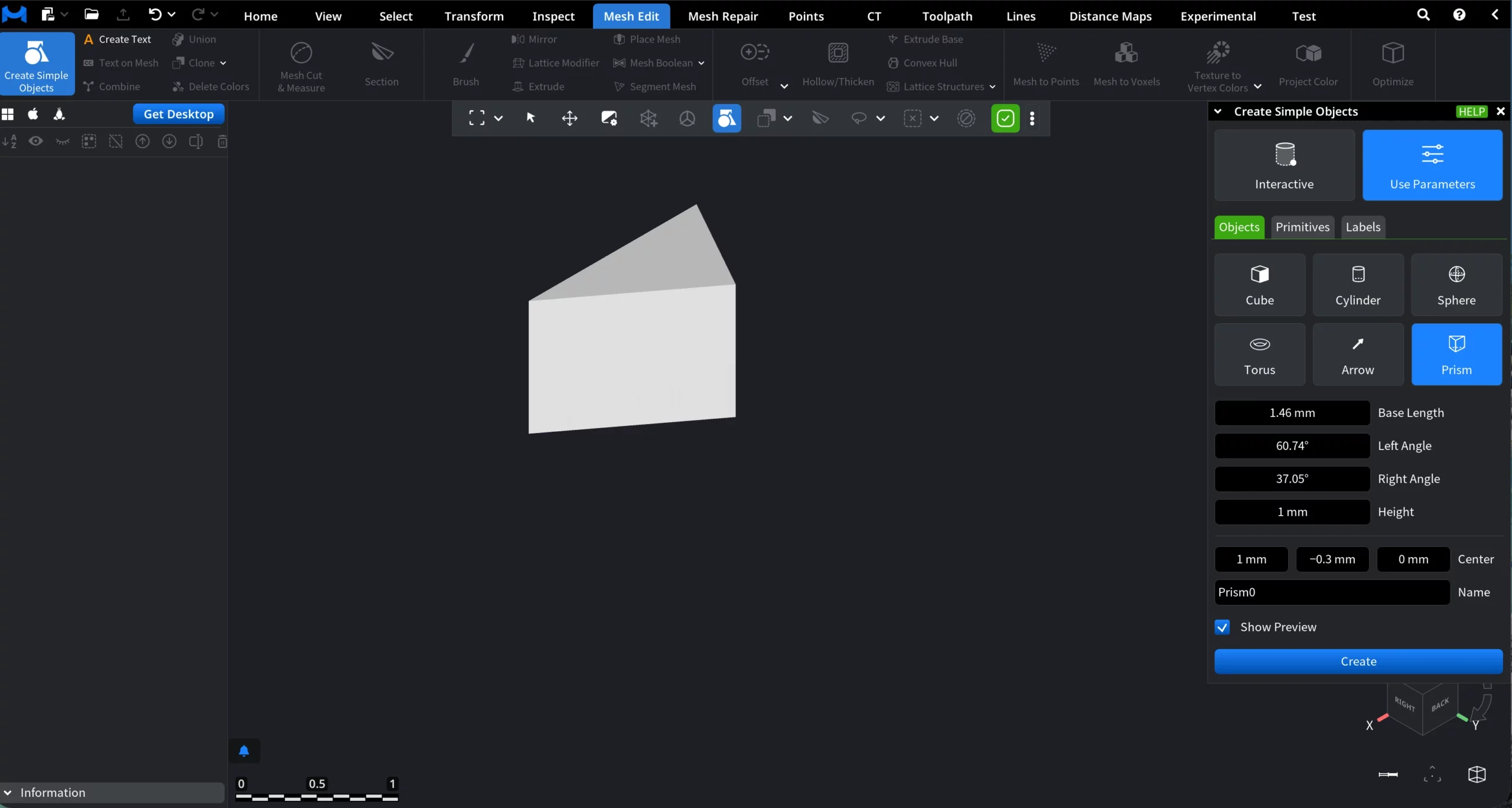
To create a Prism, configure the following parameters:
- Base Length defines the length of the base edge of the Prism.
- Left Angle sets the angle of the left side of the base profile.
- Right Angle sets the angle of the right side of the base profile.
- Height defines the extrusion height of the Prism.
- Center sets the position of the Prism’s center in the scene.
- Name assigns a name to the created Prism.
Show Preview displays a temporary preview of the Prism in the viewport before creation. Once you are satisfied with the result, click Create to finalize the process.
Primitives
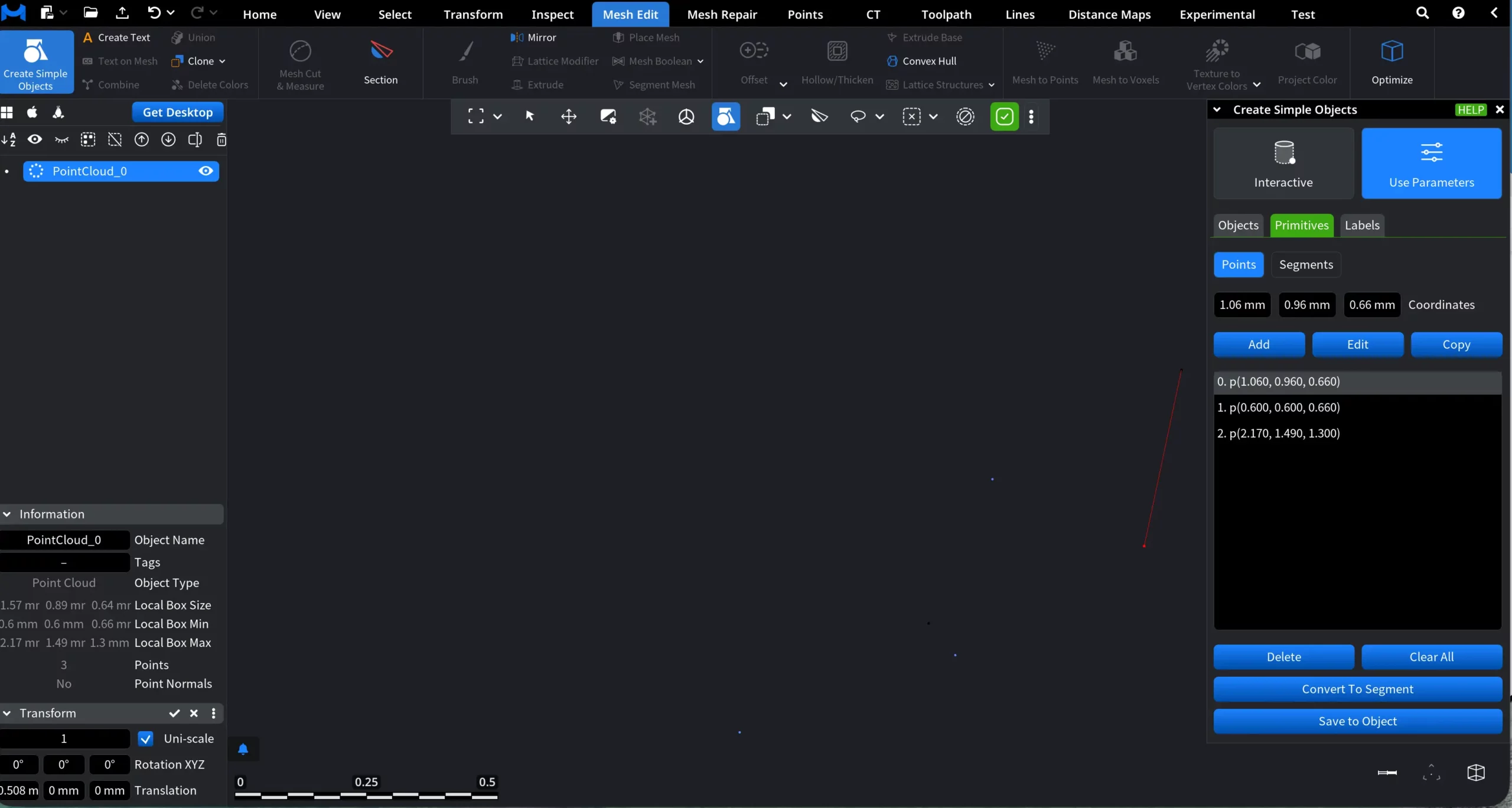
1. Points
The Points primitive allows you to define explicit 3D points using numeric coordinates. These points can later be reused to construct segments or saved as a point cloud object.
The Coordinates fields define the position of a point in 3D space:
-
X, Y, Z — numeric coordinates of the point.
You can enter values manually or adjust them directly in the input fields. Each created point appears in the list below as an indexed entry with its coordinates. Selecting a point in the list highlights it for editing or further actions.
The available buttons include:
- Add adds a new point using the current coordinate values.
- Edit updates the selected point with the values you can modify for it in the coordinate fields.
- Copy duplicates the selected point.
- Delete removes the selected point from the list.
- Clear All removes all points from the current list.
There are also two higher-level commands available:
-
Convert to Segment. When at least two points are available (there may be more), clicking Convert to Segment prompts you to select the first point (marked as (1)) and the second point (marked as (2)). After clicking Convert, a segment is created. The resulting segment becomes visible in the viewport and also appears in the Segments subsection.
-
Save to Object. When any number of points is defined, clicking Save to Object creates a point cloud object consisting of all current points. The new object is saved and added to the scene tree, where it can be reused in subsequent operations.
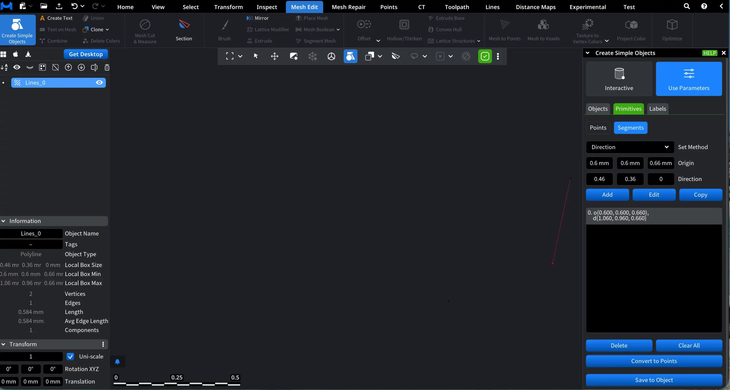
2. Segments
The Segments subsection allows you to work with line primitives created from point pairs. A segment is defined by an origin point and either a destination point or a direction vector, and is treated as a geometric primitive that can be reused for further construction.
When you switch to Segments, the panel shows the following elements:
Set Method defines how the segment is specified. You can switch between Destination and Direction:
- Origin displays the coordinates of the segment’s starting point.
- Destination displays the coordinates of the segment’s ending point. This option is available when Set Method is set to Destination.
- Direction. When Set Method is switched to Direction, the segment is defined using a starting point and a direction vector instead of an explicit destination point.
Add adds a new segment based on the selected origin and destination or direction values.
Edit allows you to modify the coordinates of an existing segment.
Copy creates a duplicate of the selected segment.
Below the controls, the segment list shows all created segments, each represented by its origin (o) and destination or direction (d) coordinates.
Additional actions are available at the bottom:
Delete removes the selected segment.
Clear All removes all segments from the list.
Convert to Points converts the segment endpoints back into individual points. These points become available in the Points subsection.
Save to Object saves the currently selected segment as a separate Lines object. The resulting object appears in the scene tree and can be used in subsequent operations.
3. Labels
The Labels section allows you to create text annotations that can be placed in the scene to mark, describe, or reference objects and locations. The Labels panel provides the following controls:
Label defines the text content of the label. This text will be displayed directly in the viewport.
Position specifies the 3D coordinates where the label will be placed in the scene.
Pivot point controls the anchor point of the label relative to its text.
Show Preview, when enabled, displays a temporary preview of the label in the viewport before it is created.
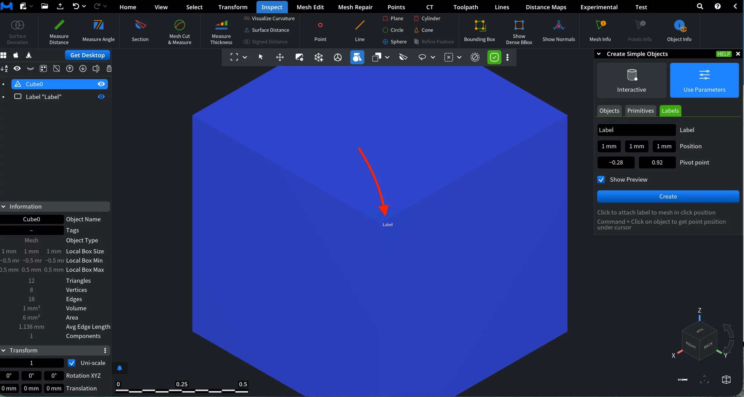
Create finalizes the label and adds it to the scene.
MeshInspector makes creating simple forms both quick, effective, and intuitive.