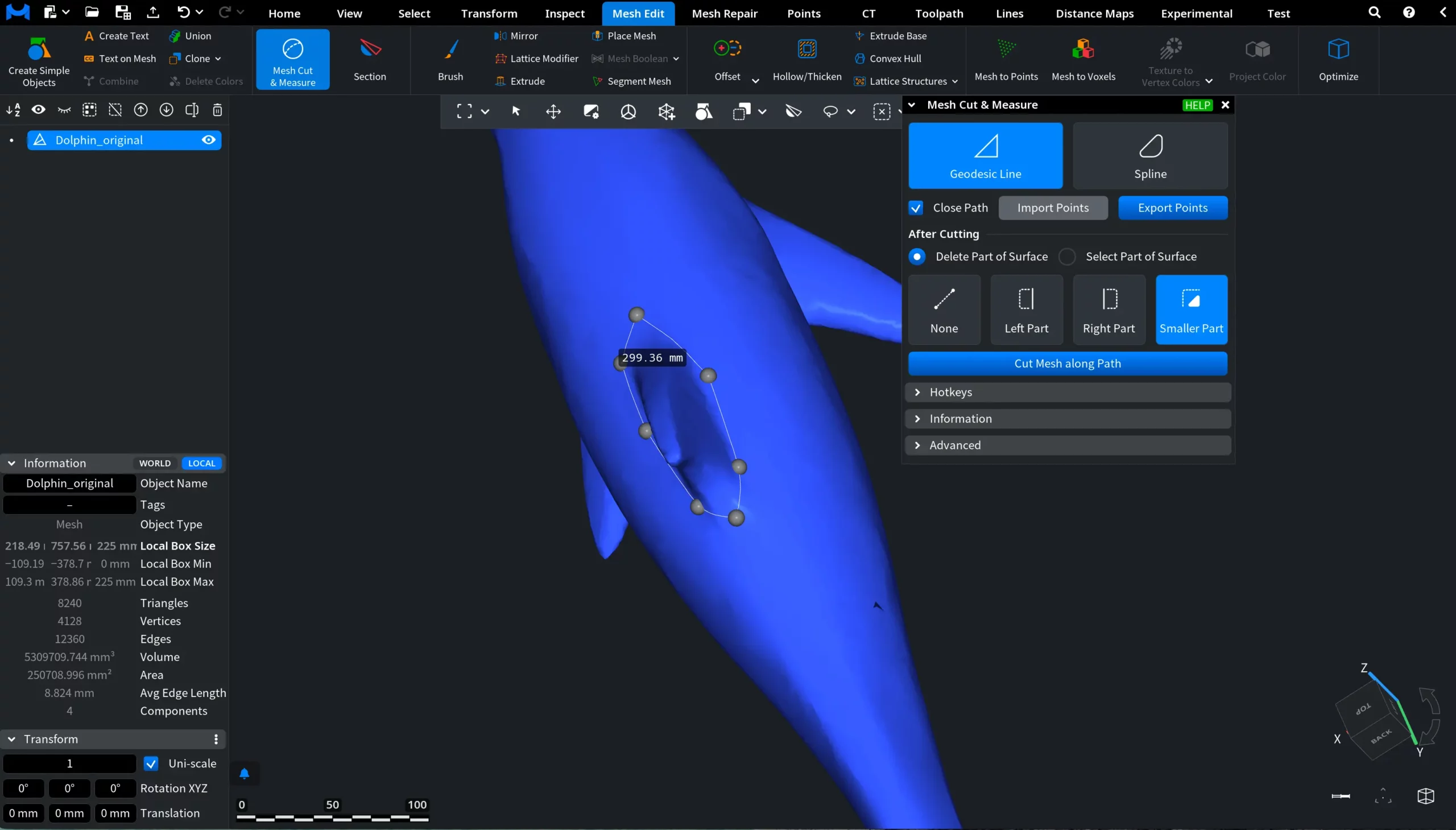
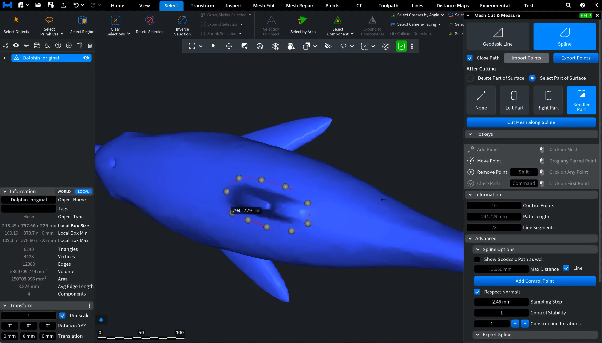
The Mesh Cut & Measure tool, available under the Mesh Edit tab (as well as under Inspect), allows you to slice meshes along a custom path. The path can be either geodesic or spline-based. The tool also measures the path length. Here is where to find it.

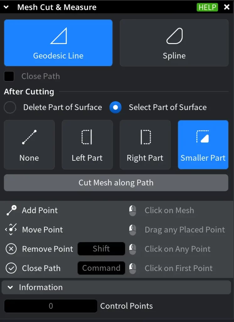
After activating Mesh Cut & Measure, a dedicated control panel appears. The tool provides two cutting modes: Geodesic Line and Spline:
- Geodesic Line constructs the contour along the shortest surface path between consecutive control points.
- Spline creates a smooth contour based on spline interpolation. Unlike Geodesic Line, it does not follow the shortest surface path between control points. Instead, the curve shape is defined by the placement and adjustment of the control points, allowing smoother and more flexible cuts.
The available settings and interaction workflow depend on the selected mode.
Geodesic Line
If you choose Geodesic Line, the cutting contour follows the shortest surface segment between each pair of consecutive points. Place points directly on the mesh to build the path:
- Click on the mesh to add a point.
- Drag a point to adjust the contour.
- Shift + click a point to remove it.
The path automatically adapts to the surface curvature and updates after each change. At least two points are required to perform a cut. If you choose to Close Path, the path becomes a closed boundary on the surface. However, even after the path is closed, you can still move the points that constitute it.
After Cutting
Here, you choose how the mesh should be handled once the contour is created.
Delete Part of Surface defines how geometry is handled after the cut:
- None does not delete any geometry. Instead, it splits the mesh along the contour and selects the newly created edges. To convert the split parts into separate objects, go to Mesh Repair and click To Components after cutting.
- Left Part removes the surface on the left side of the contour. The direction of the contour is defined by the first and second points.
- Right Part removes the surface on the right side of the contour.
- Smaller Part removes the smaller region.
Select Part of Surface selects the corresponding region instead of deleting it.
Information
The Information panel displays real-time data about the constructed path:
- Control Points displays the total number of user-placed points defining the contour.
- Path Length shows the total length of the constructed path passing through all points.
- Line Segments shows the number of mesh triangles the geodesic path crosses. Within each triangle, the path is represented as a straight segment.
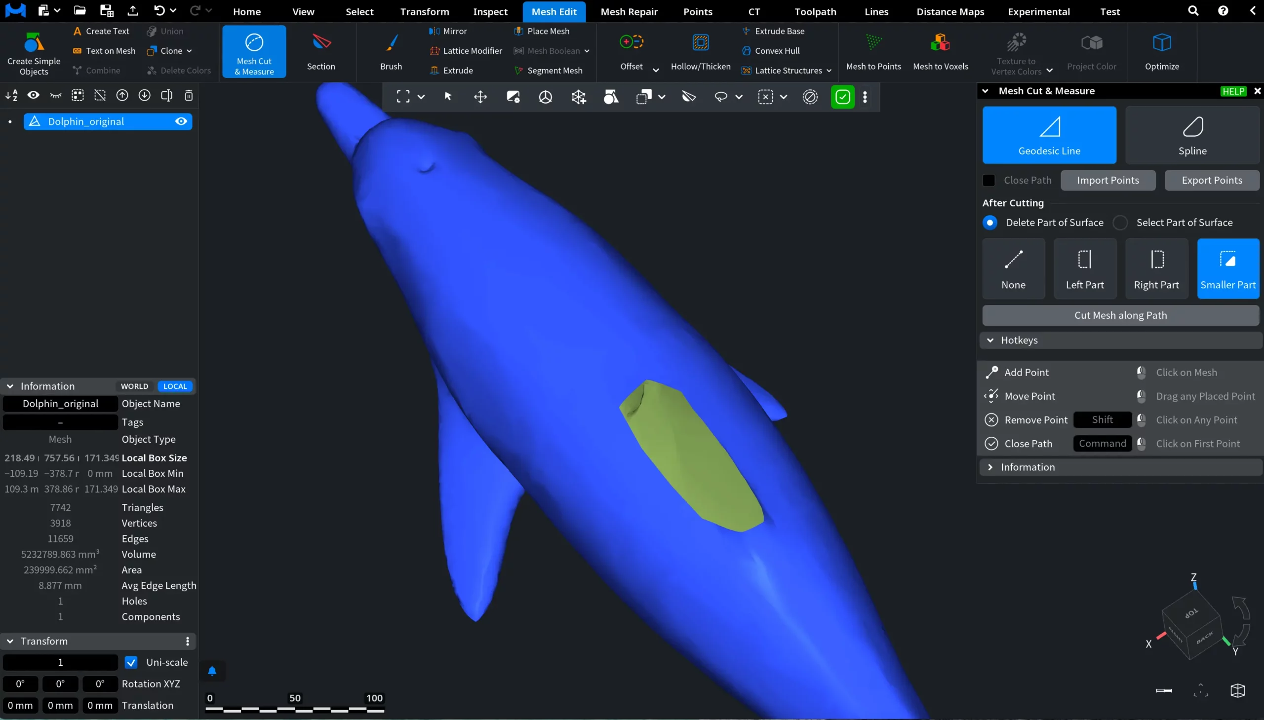
Cut the Mesh
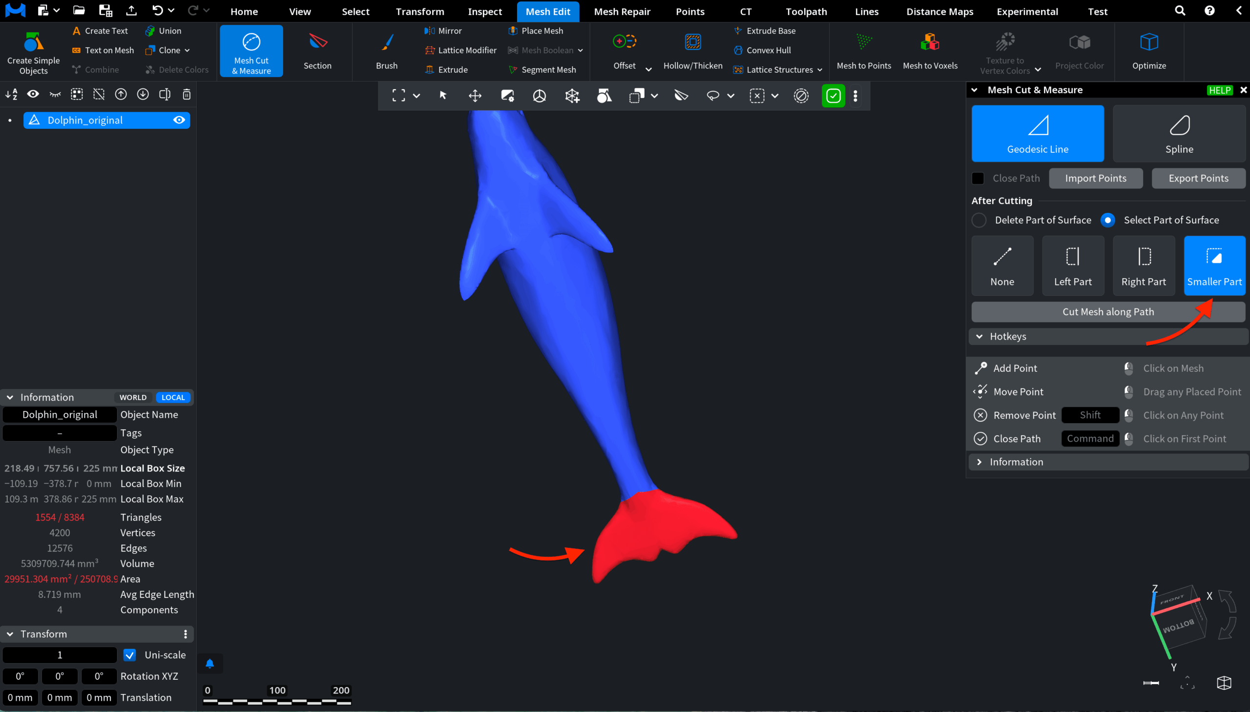
Click Cut Mesh along Path to apply the operation. MeshInspector splits the mesh along the contour and performs the selected action. In the screenshot below, the path is closed, Delete Part of Surface is enabled, and Smaller Part is selected.
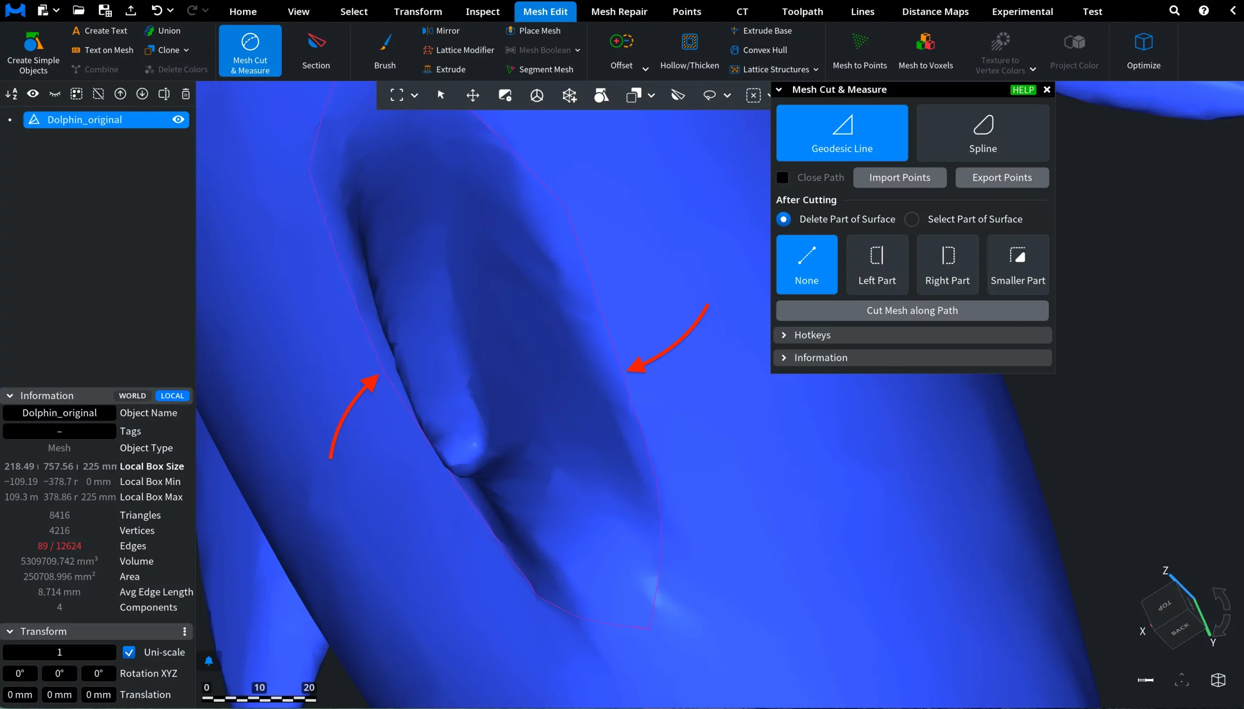
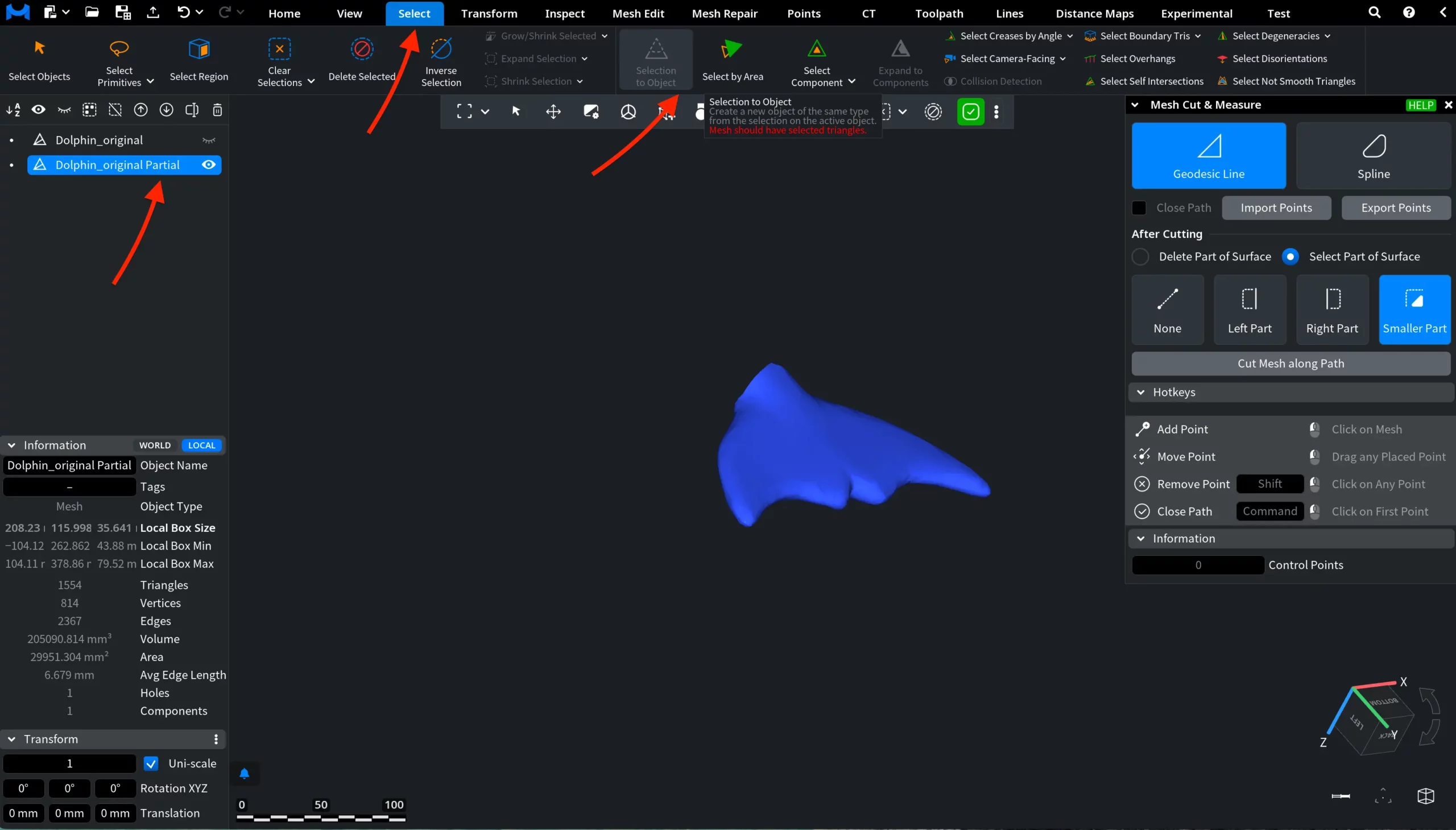
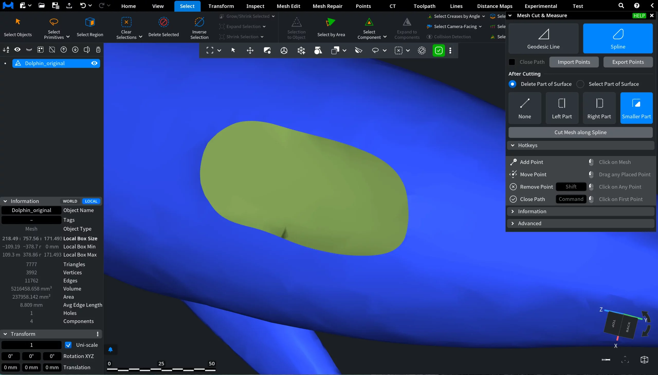
Another example shows what happens if you choose Select Part of Surface with Smaller Part enabled. As you can see, the smaller part, i.e., the tail, is highlighted in red. That means all the triangles constituting it are selected.
To create a separate object based on this selection, go to Select and click on Selection to Object.
Advanced Settings for Geodesic Line
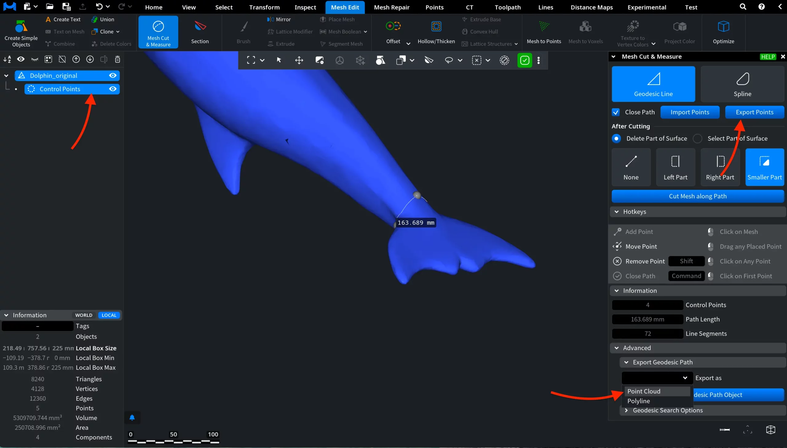
In the Advanced section of Mesh Cut & Measure, you can find two additional features: Export Geodesic Path and Geodesic Search Options.
Export Geodesic Path
The Create Geodesic Path Object button creates a new scene object representing the current path.
Before creating the object, select its type in Export as:
- Polyline creates a line object following the geodesic contour.
- Point Cloud creates a point cloud along the path with normals.
The created object appears in the Scene Tree and can be edited or exported independently of the mesh.
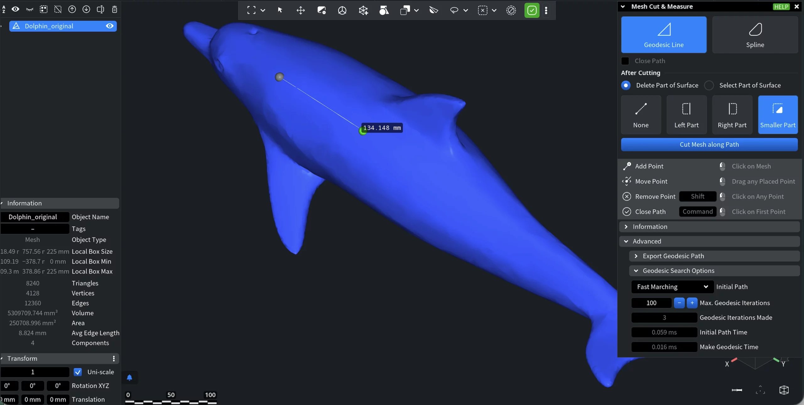
Geodesic Search Options
The Geodesic Search Options section controls how MeshInspector constructs the geodesic path on the mesh surface.
Initial Path defines the method used to build the initial approximation of the geodesic path between control points.
- Dijkstra bidir. performs a fast bidirectional search. Generates a stable initial path but not always the shortest one.
- Dijkstra A* is faster for nearly straight paths. Works well when points are close and the path does not strongly curve.
- Fast Marching produces a path closer to the true geodesic but requires more computation time.
- Max. Geodesic Iterations specifies the maximum number of refinement iterations applied after the initial path is constructed. More iterations improve accuracy but increase computation time.
Timing indicators (shown when the path consists of a single segment between two points):
- Geodesic Iterations Made shows the actual number of refinement iterations performed.
- Initial Path Time shows the time spent building the initial path approximation between the two points.
- Make Geodesic Time shows the time spent refining the path to the final geodesic.
Spline
Spline mode allows you to define the cutting contour manually instead of relying on the shortest surface path. Control points define a smooth curve that is projected onto the mesh surface and then converted into the cutting contour. After projection, the mesh is processed the same way as in Geodesic Line mode, so all cutting options and measurements behave identically.
Only the path construction differs. Once the operation is committed, you will see the cut with smoother edges.
Advanced Spline Options
These parameters control how the spline is projected and converted into the cutting contour on the surface:
- Show Geodesic Path as well displays the resulting projected contour used for cutting.
- Max Distance limits how far the spline may deviate from the surface during projection.
- Add Control Point inserts an additional control point on the projected geodesic path where it deviates the most from the spline.
- Respect Normals improves projection stability on sharp curvature.
- Sampling Step controls projection density.
- Control Stability stabilizes the curve when editing points.
- Construction Iterations refines the projected contour.
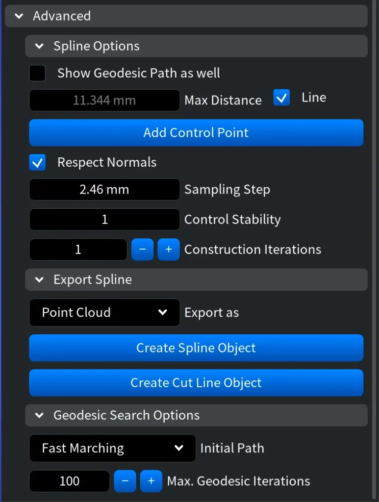
Export Spline
Export Spline creates an object representing the projected spline curve on the mesh surface:
- Polyline exports the curve as a line object.
- Point Cloud exports sampled spline points with normals.