When preparing models for manufacturing or 3D printing, the geometry frequently requires additional processing before fabrication. Scanned or organic shapes may contain open boundaries, unstable support surfaces, or undercuts that complicate placement on the build platform. Such models must be properly oriented and converted into a manufacturable model.
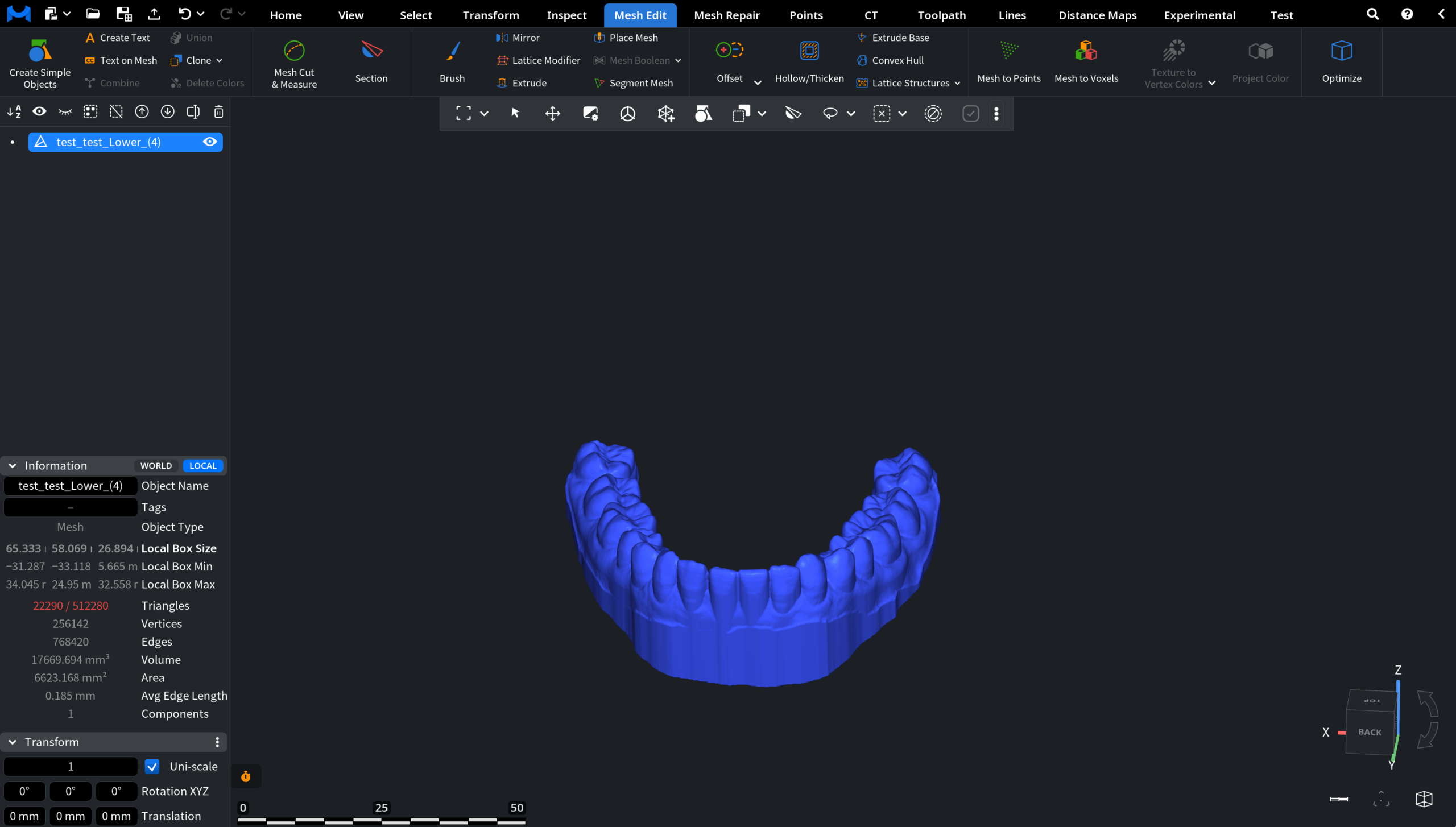
The Extrude Base tool, located under the Mesh Edit tab, creates a closed and base-supported model suitable for fabrication. It does so by generating a planar support base relative to a selected Print Direction, optionally correcting undercuts. This allows the object to be placed securely on the build platform and prepares it for further processing.

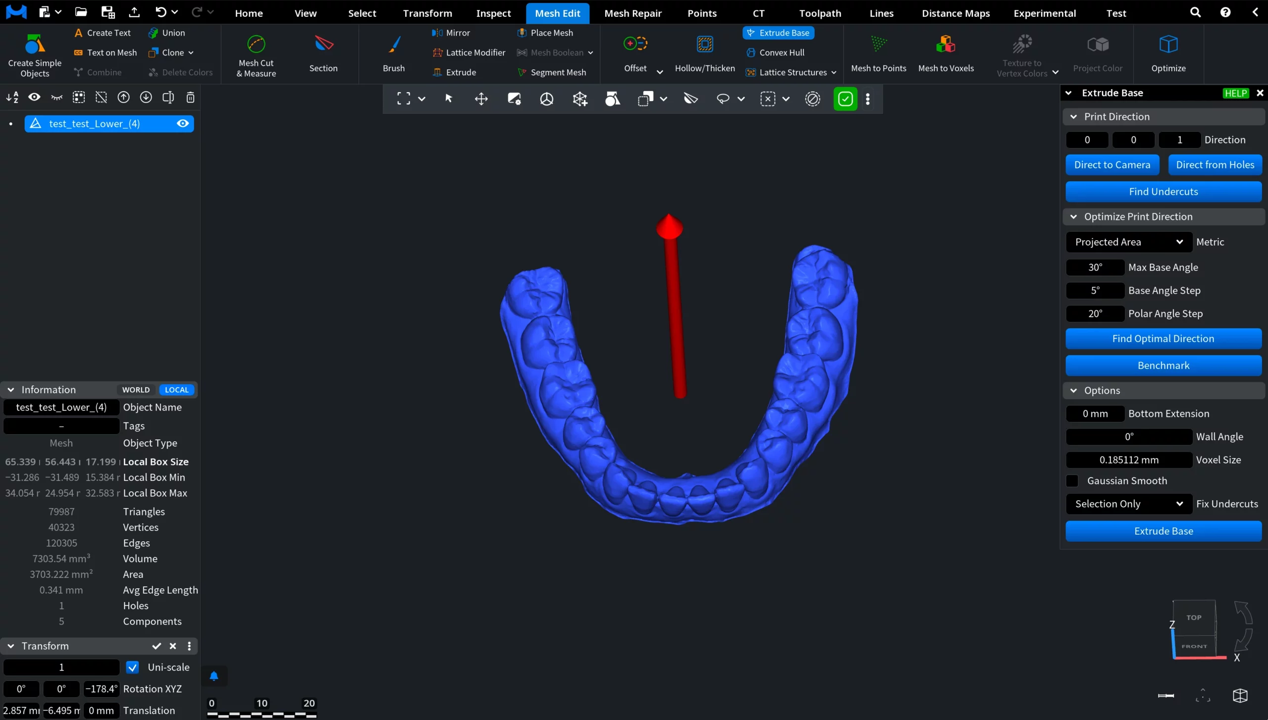
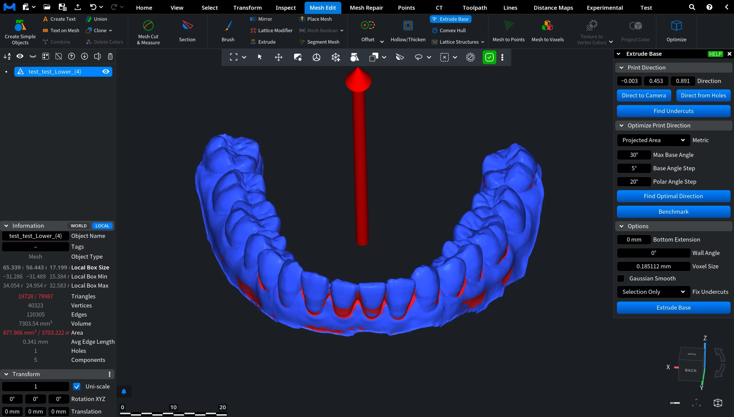
After activating Extrude Base, an arrow appears in the viewport indicating the Print Direction. The base is generated in the opposite direction of the red arrow. Also, a dedicated Extrude Base panel opens on the right, containing controls for orientation analysis, undercut detection, and base generation settings.
Print Direction and Undercuts
The red arrow indicates the Print Direction. The base itself is generated in the opposite direction of this arrow. This Direction defines which areas become the bottom of the model and which regions are treated as undercuts. Choosing it correctly is essential for stable placement and proper fabrication.
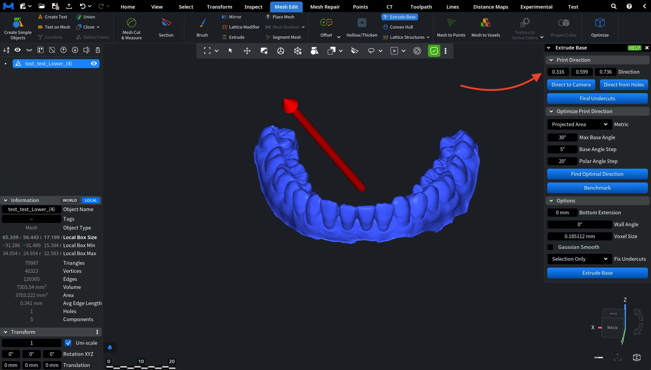
Direction Vector (Three Components)
The Print Direction is defined by three numeric components (X, Y, Z). These values represent the direction vector used for base extrusion. Modifying the vector changes the reference build orientation. The arrow in the viewport updates accordingly, allowing you to visually evaluate the orientation before modifying the mesh.
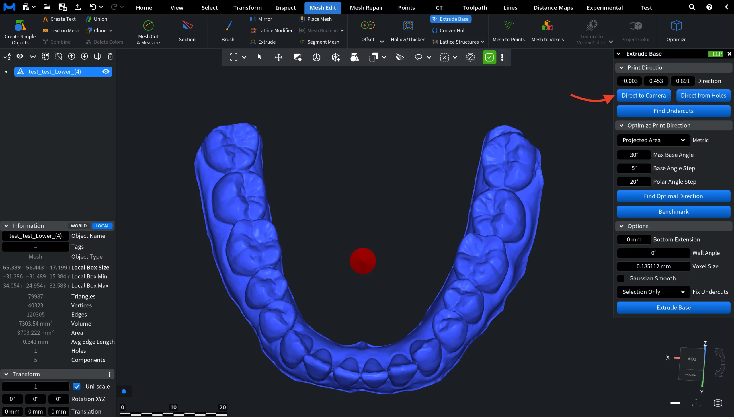
Direct to Camera
Direct to Camera aligns the Print Direction with the current camera view. This is especially useful when the model is already visually oriented in the viewport and you want the extrusion to follow what appears as “down” on screen before running Find Optimal Direction.
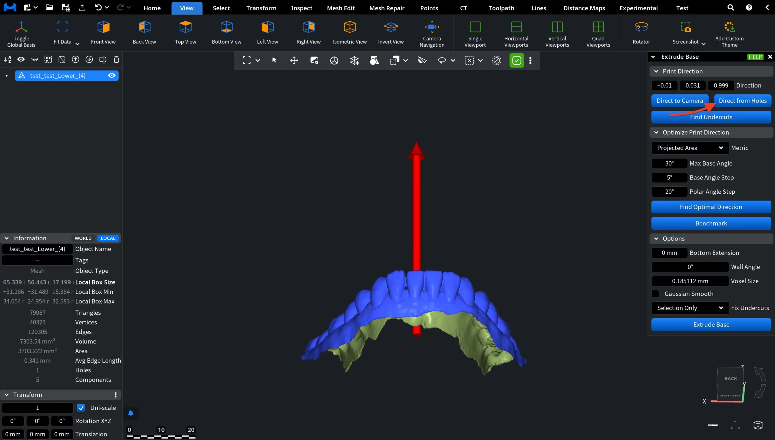
Direct from Holes
Direct from Holes automatically determines a Print Direction based on detected holes or open boundaries. It analyzes these openings and suggests a direction that typically corresponds to the natural base orientation of scanned objects.
Find Undercuts
Find Undercuts highlights regions that form undercuts relative to the selected Print Direction. These areas exceed the defined wall angle and may prevent stable fabrication from that orientation. Such regions may require correction, smoothing, or reorientation before generating the base.
Optimize Print Direction
This feature evaluates multiple candidate Directions and selects the one that minimizes undercuts according to the chosen metric before generating the base.
Metric
The selected Metric defines what MeshInspector's algorithm tries to minimize:
- Area minimizes the total area of all undercut faces.
- Projected Area minimizes the visible undercut area when viewed along the direction.
- Projected Area Approx provides you with a faster approximation of the projected area metric.
Angular Settings
- Max Base Angle limits how far the base orientation may tilt.
- Base Angle Step defines the rotation step around the base axis.
- Polar Angle Step sets the step size when sampling directions in space.
Find Optimal Direction
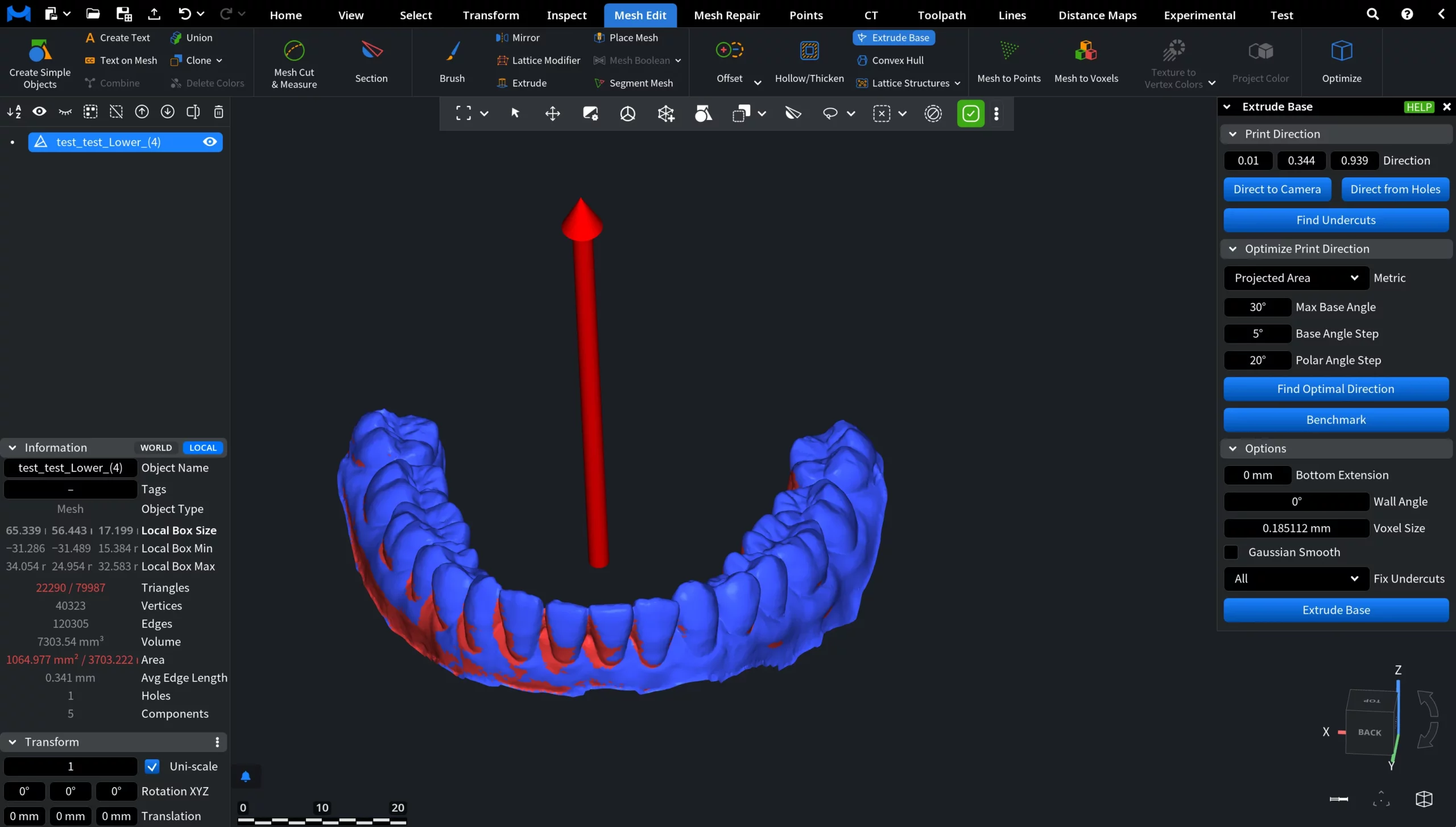
Find Optimal Direction automatically calculates a direction that minimizes undercuts according to the selected metric for the model. MeshInspector analyzes the geometry and rotates the direction arrow so that problematic areas, i.e., undercuts, are minimized according to the selected metric. This functionality helps orient the model in a way that improves manufacturability and reduces the need for corrections before creating the base. You can see how it works in the screenshots below.
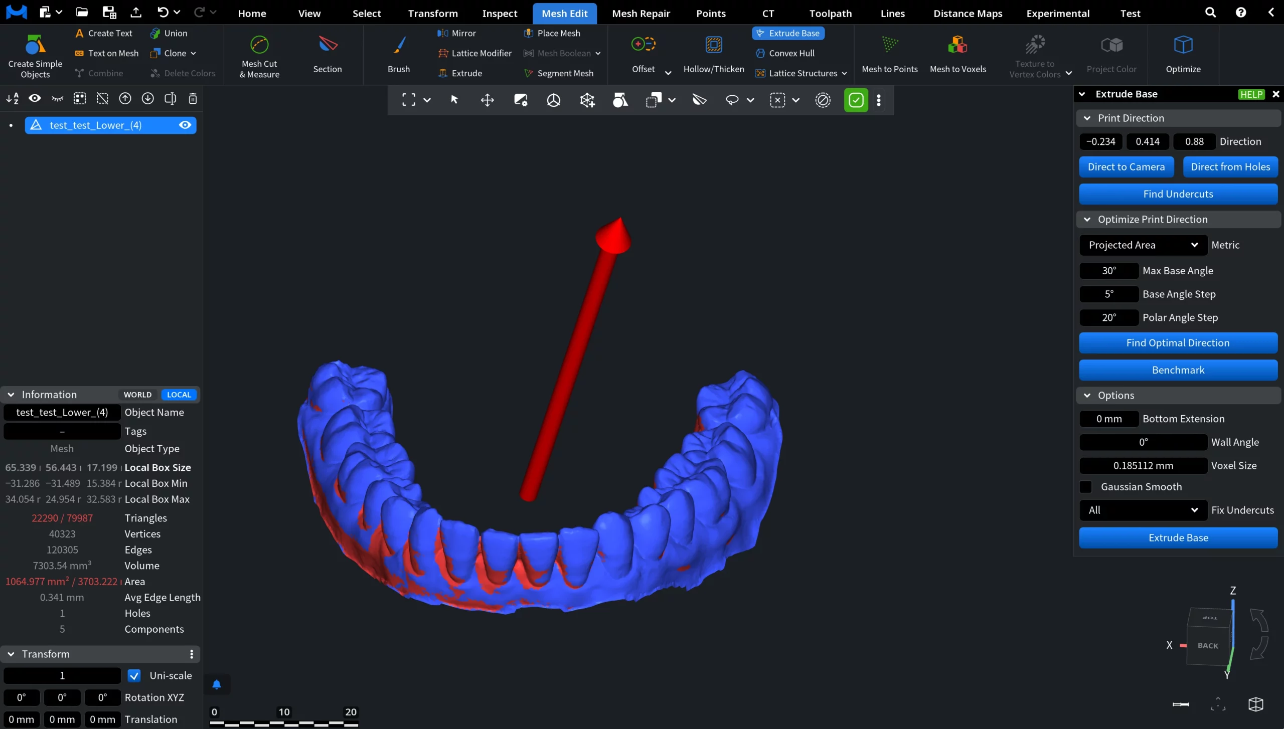
Before optimization
The Print Direction is set arbitrarily. Detected undercuts appear on many visible outer surfaces, which would lead to fabrication issues and unstable placement.
After optimization
Find Optimal Direction reorients the direction toward a manufacturing-friendly position.
Options
The parameters in the Options section control how MeshInspector modifies the model geometry. They affect smoothing, angle tolerance, and which undercuts will be corrected before generating the base.
Bottom Extension
Bottom Extension adds additional material below the lowest detected support level before the base is created.
This helps ensure stable placement and prevents thin contact edges between the model and the base.
- Higher values mean thicker supporting platform area.
- Lower values mean minimal contact with the base.
Wall Angle defines the maximum allowed slope relative to the print direction. If a surface is steeper than this angle, it is treated as an undercut and will be corrected (depending on setting).
- Small angle means more surfaces considered problematic.
- Large angle means only deep overhangs corrected.
Voxel Size controls the internal resolution used during undercut correction.
- Smaller voxel size means higher accuracy and finer details preserved.
- Larger voxel size means faster processing but rougher correction.
Gaussian Smooth applies smoothing to corrected regions after undercuts are removed. This prevents sharp artifacts and produces a more natural transition to the base.
- Enabled means softer and smoother surface transitions.
Disabled means sharper, more mechanical geometry.
Fix Undercuts determines which detected undercuts will be corrected before base generation.
- All corrects all detected undercuts according to the selected parameters.
- Selection Only fixes only selected areas.
This allows preserving important anatomical features while correcting only problematic regions.
Extrude Base
Clicking Extrude Base performs the final operation, i.e., a planar supporting base is generated, producing a closed mesh. The geometry is rebuilt according to the chosen parameters and detected undercuts are corrected.
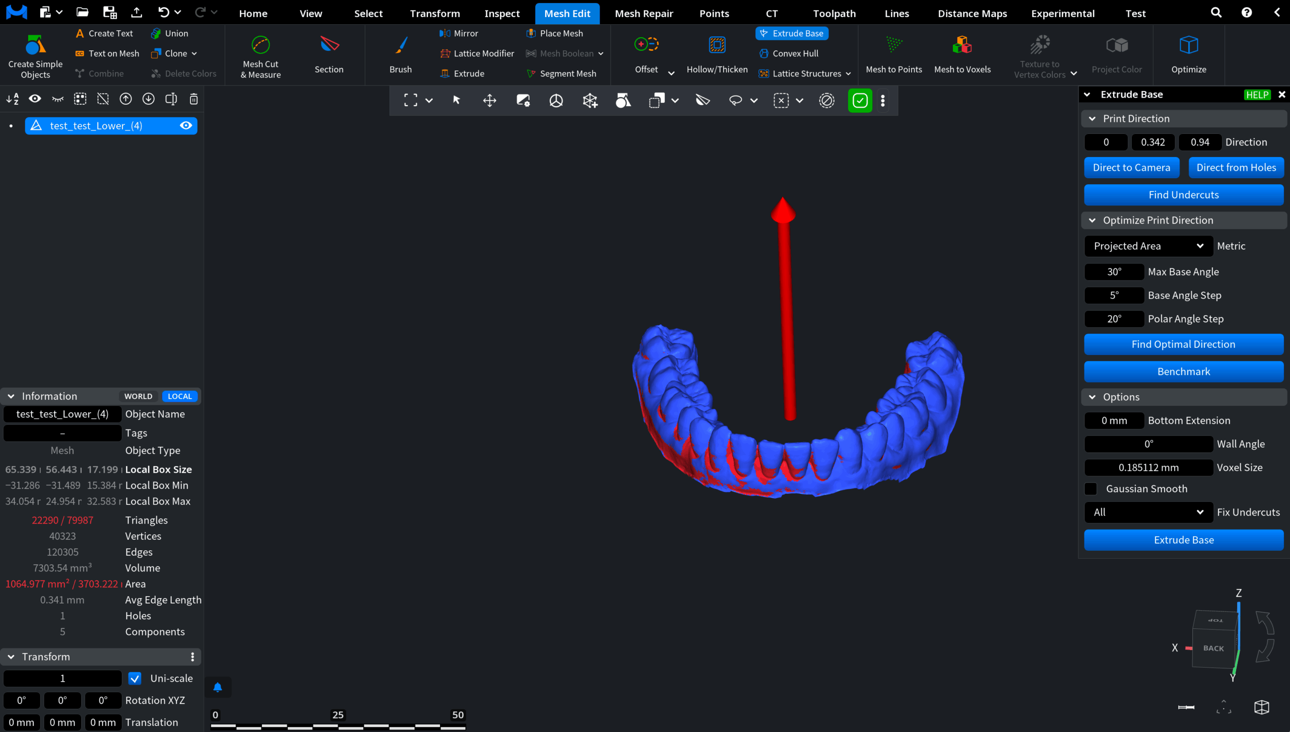
Before Extrude Base
The model contains open boundaries and problematic regions relative to the selected Print Direction. These areas would prevent stable placement on the build platform and lead to fabrication artifacts.
Before running the operation, the following settings were used:
- Optimized Print Direction. The model was oriented to minimize undercuts.
- Fix Undercuts. All. All problematic overhangs were corrected to ensure manufacturability.
- Wall Angle. 50°. Only steep surfaces were treated as undercuts, preserving anatomical detail.
- Bottom Extension. 0.3 mm. A thin supporting platform was added for stable placement.
- Gaussian Smooth. Enabled. Transitions between corrected regions and original geometry were softened to produce a smooth and manufacturable base suitable for dental models.
After extrusion
A solid base is created and the mesh becomes a closed and base-supported model suitable for fabrication. The object can now be placed stably on the build platform and used for further manufacturing or 3D printing.
The model is now properly oriented, corrected, and base-supported. This makes it ready for reliable downstream fabrication.