The Lattice Structures tool in MeshInspector is used to generate controlled internal structures inside a 3D model. It allows users to balance weight, strength, and material usage for manufacturing and further processing by creating repeating lattice patterns. The tool also provides a live preview and adjustable parameters so you can evaluate and refine your structure before applying it.
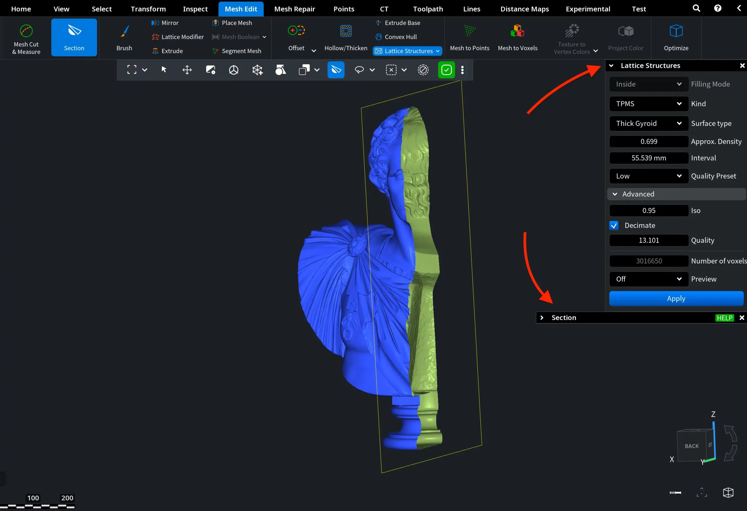
You can find Lattice Structures under the Mesh Edit tab.

When the tool is activated, Section is opened alongside it. This is important because the lattice is generated inside the model, and the cross-section view lets you inspect the internal volume and monitor how the structure forms in real time.
With the cross-section enabled, we can start using Lattice Structures. First, we select the Filling Mode.
Filling Mode
Filling Mode determines which part of the model’s internal volume will be filled with the lattice structure.
Inside
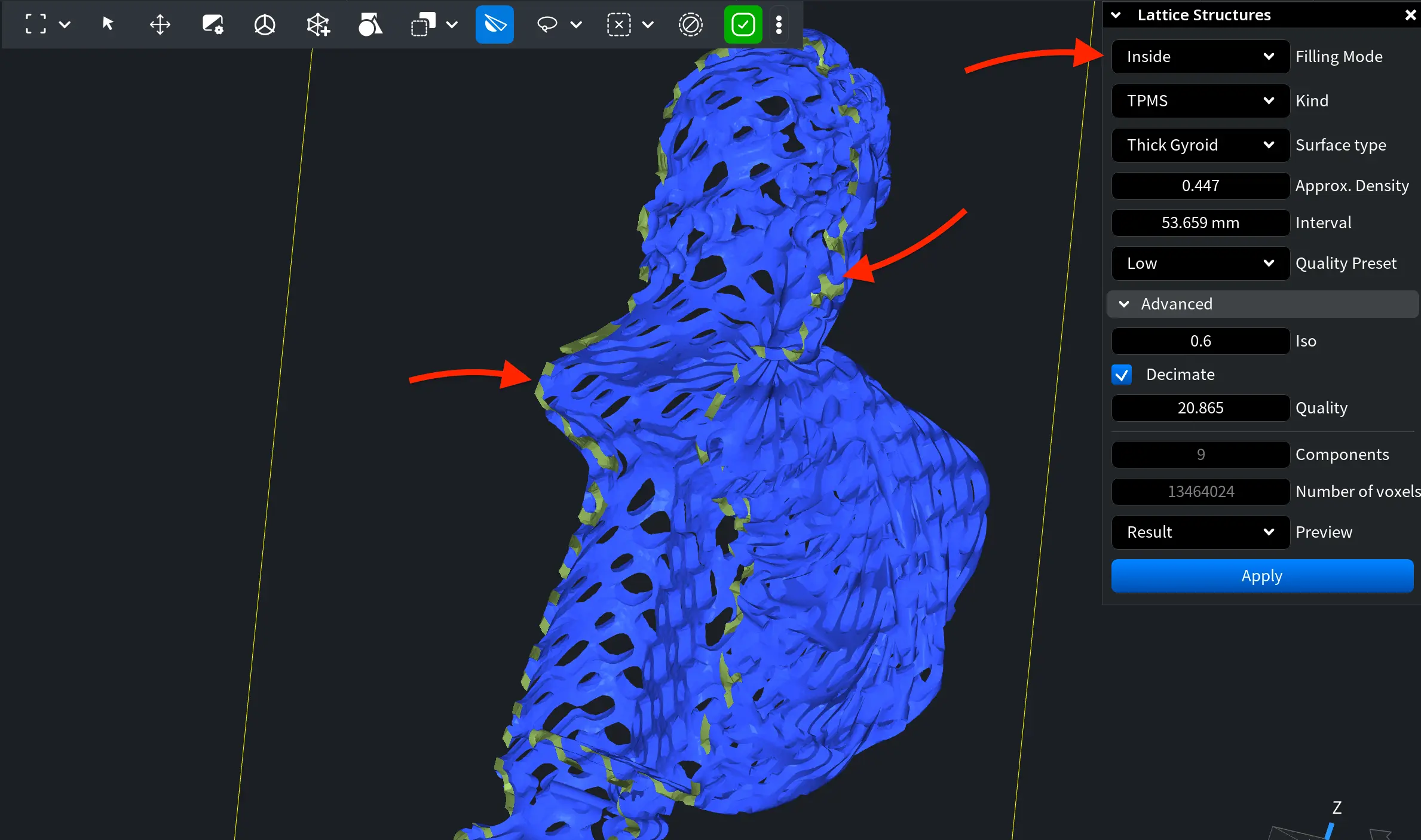
With Inside selected as the Filling Mode, the lattice is generated throughout the entire internal volume of the model, as shown below.
The Inside Filling Mode remains available when you work not only with solid meshes, but with meshes that feature an outer shell and an internal cavity. After applying it, the internal volume will be filled with the selected structure, as shown below.
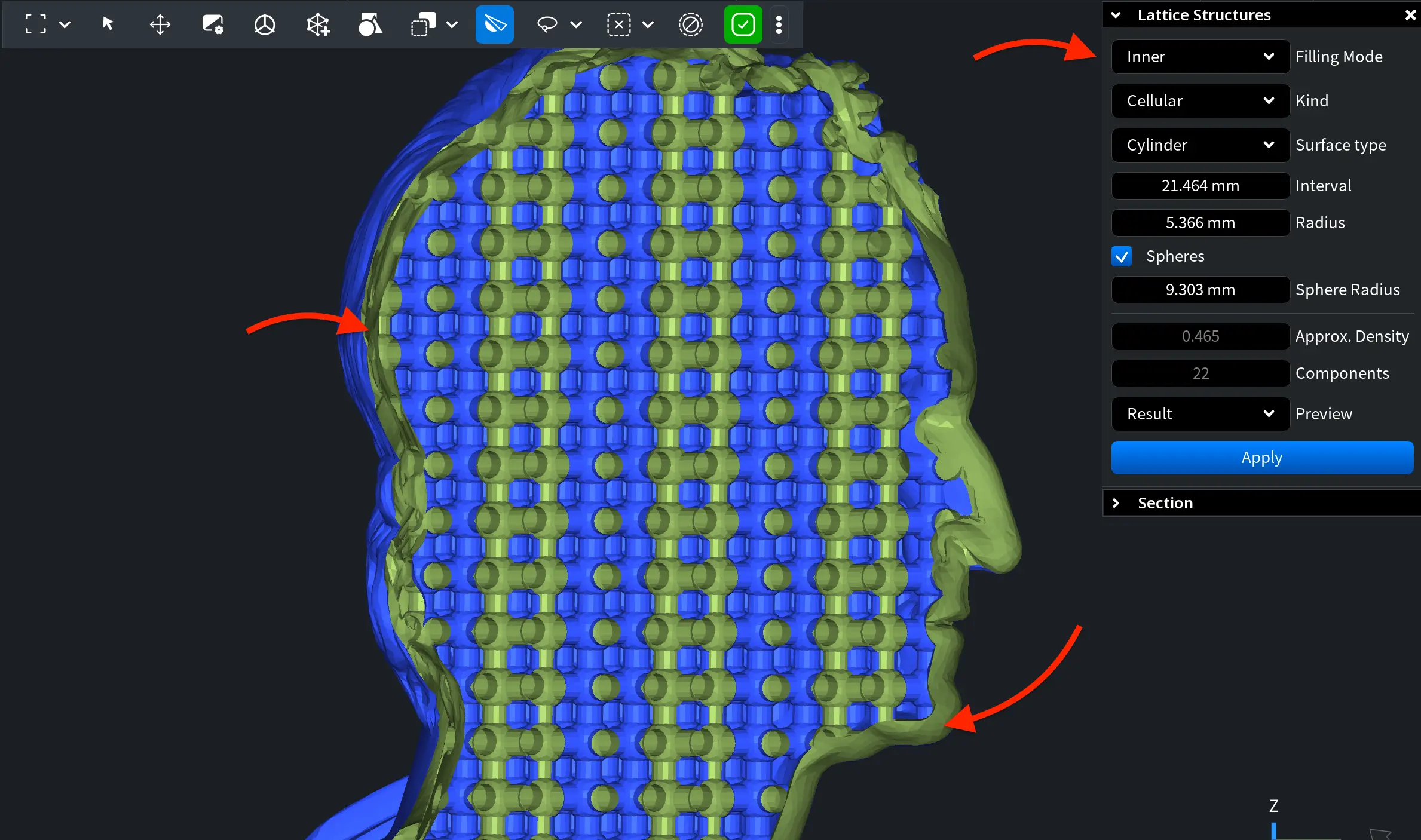
Inner
With Inner selected as the Filling Mode, the lattice is generated only within the shell thickness of the model rather than across its full internal volume. For this mode to work, the mesh must contain exactly two components: an outer shell and a second shell located inside it (otherwise, Inner will not be available). The inner shell defines the internal cavity where the lattice will be generated.
You can verify whether the mesh meets this condition using Mesh Healer. If the required structure is not present, repair the mesh using Mesh Healer before generating the lattice.
Kind
Kinds define the type of lattice structure used to fill the model. MeshInspector provides two kinds: TPMS and Cellular.
TPMS
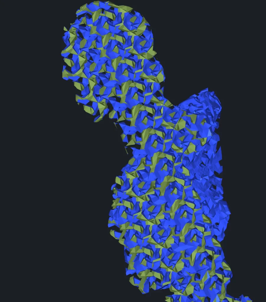
TPMS (Triply Periodic Minimal Surface) creates a smooth continuous surface that repeats in 3D space and divides the volume into interwoven regions. That is, it forms an organic-looking porous structure that distributes material evenly. As such, it is well suited for lightweight parts and uniform stress distribution.
Cellular
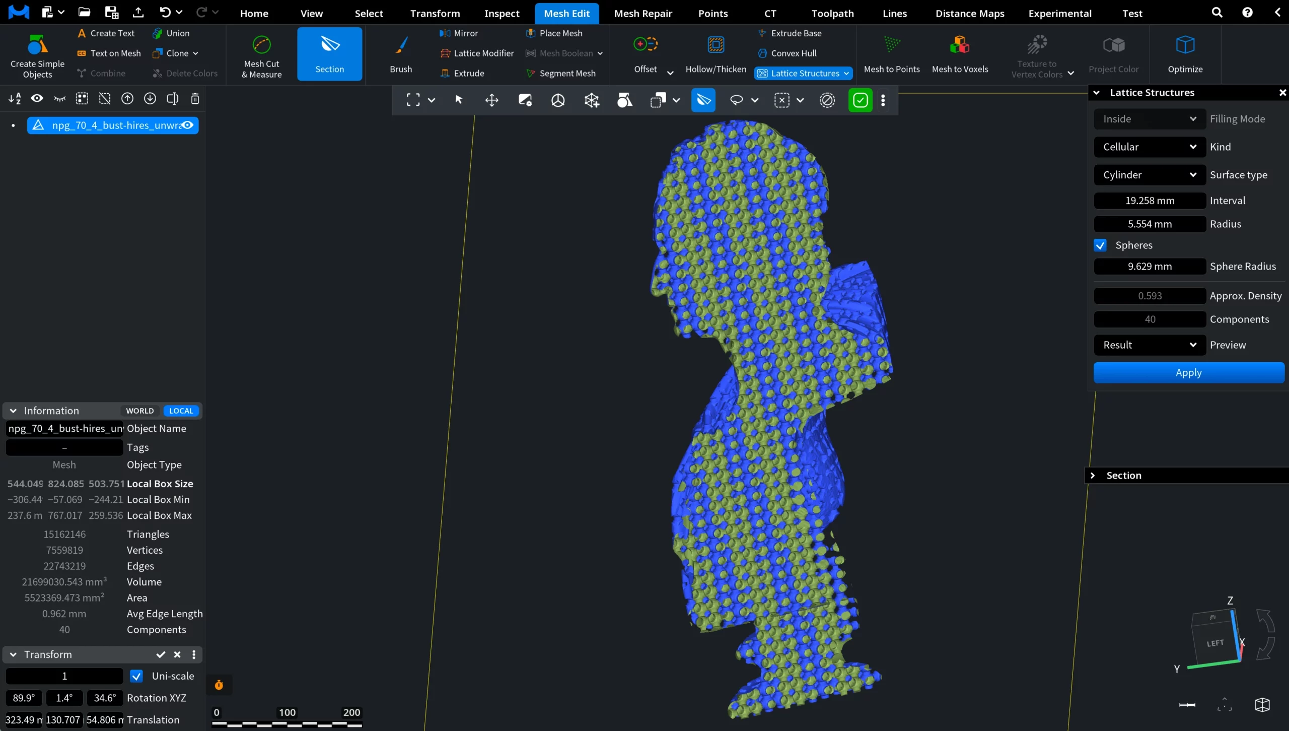
Cellular creates beam-based lattices. Instead of smooth surfaces, the interior is built from connected repeating beams forming a grid. This produces a more mechanical reinforcement structure where stiffness and rigidity are controlled by beam spacing and thickness.
Settings with TPMS
TPMS Surface Types
If TPMS is selected as your Kind, you can choose one of four surface types. Each defines how the continuous minimal surface is shaped inside the volume and therefore how material is distributed.
-
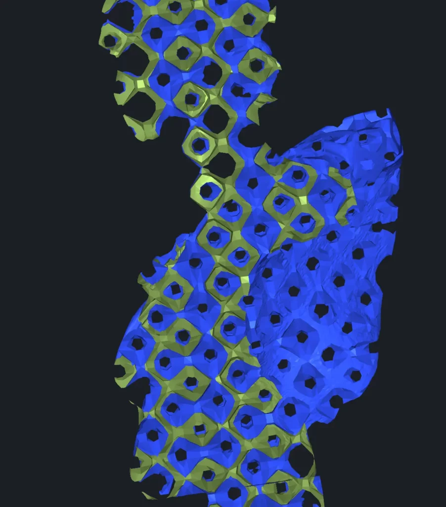
Rectangular. A grid-like periodic minimal surface (Schwarz-P type). It creates regular openings and balanced material distribution, suitable for general lightweight structures.
-
Thick Rectangular. A rectangular TPMS surface with increased wall thickness. It provides higher strength and lower porosity while preserving the same periodic pattern.
-
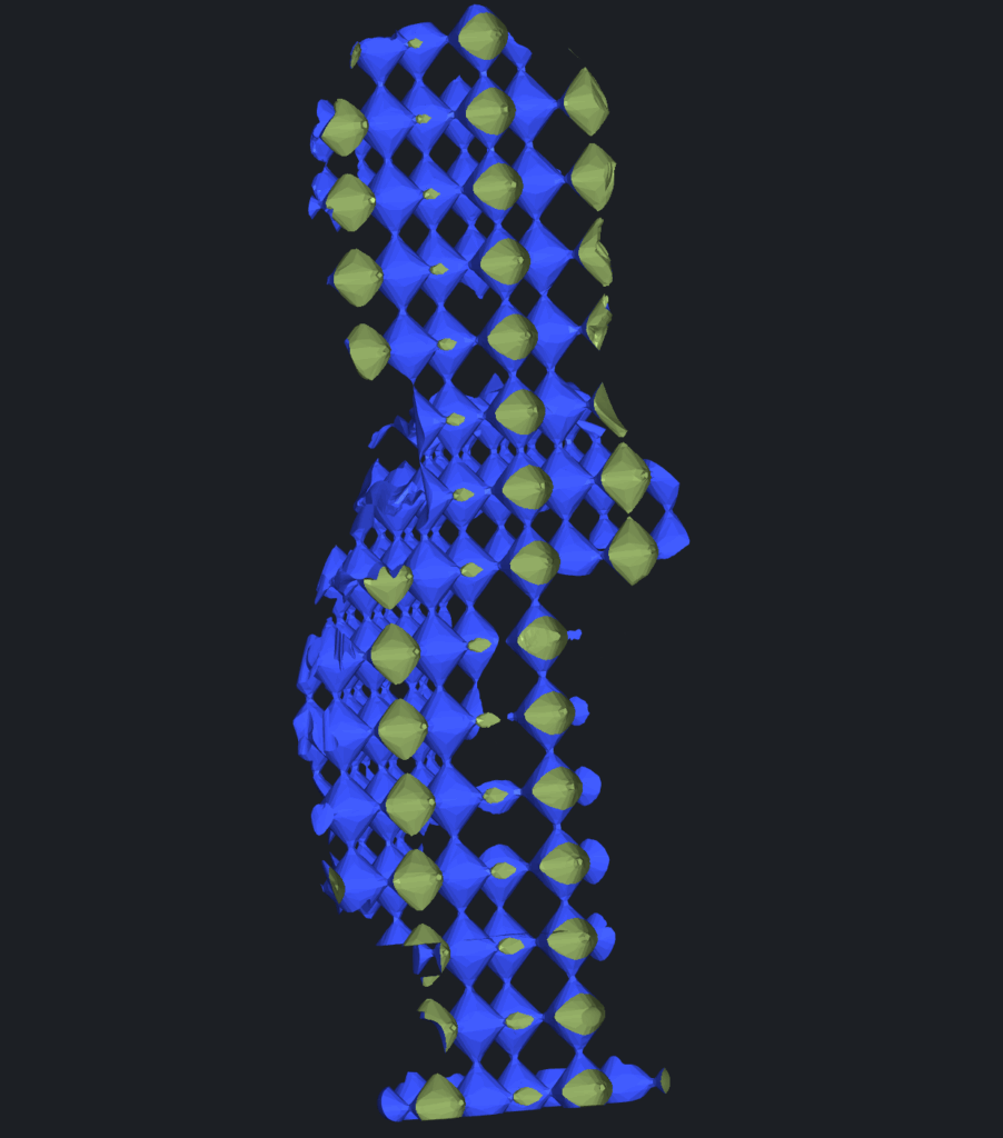
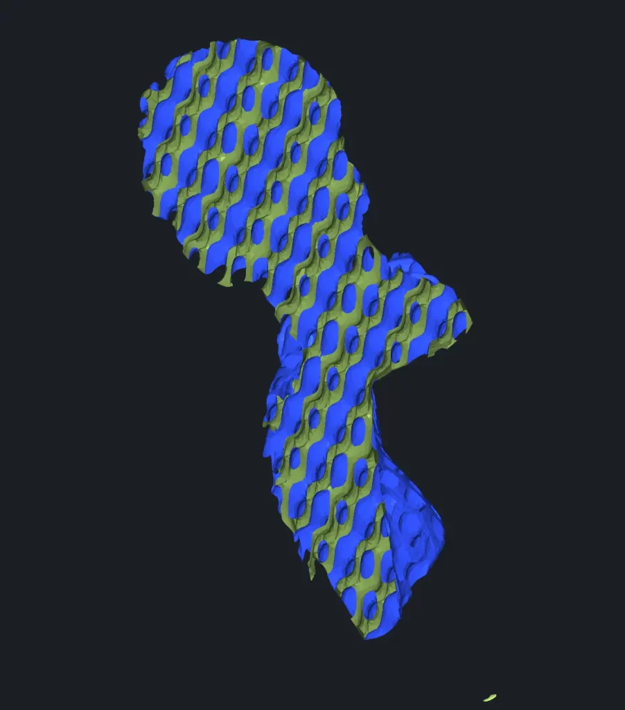
Double Gyroid. A complex interwoven minimal surface consisting of two intertwined channels. It distributes stress smoothly in all directions and is often used when uniform mechanical behavior is required.
-
Thick Gyroid. A reinforced gyroid with thick walls. It produces reinforced internal support with thicker walls while maintaining smooth transitions and continuous connectivity.
Other Options with TPMS
Approx. Density controls how much material the lattice occupies inside the model. Higher values produce a denser, stronger structure with less empty space, while lower values create a lighter and more porous interior.
Interval defines the scale of the repeating lattice pattern. Smaller values generate a finer structure with smaller cells, while larger values create bigger cells and reduce material usage.
Quality Preset controls the resolution of lattice generation. Higher presets produce smoother and more accurate geometry but require more computation time and memory. Lower presets calculate faster but generate a coarser structure. You can choose between Low, Standard, and High.
The Advanced section provides more precise control over how the TPMS lattice is generated and optimized. These parameters affect both the physical properties of the structure and the computational cost.
ISO controls the iso-surface level used to construct the lattice. In practice, it changes the resulting material volume: higher values produce thicker surfaces and a heavier structure, while lower values make the lattice lighter and more open.
Decimate reduces the polygon count of the generated filling surface after creation. This helps decrease file size and improve performance.
Quality defines the resolution of the surface approximation. Increasing this parameter improves smoothness and accuracy but increases computation time and memory usage. It provides more granular control than Quality Preset, which updates automatically when Quality is adjusted.
Components shows the number of connected lattice parts detected in the current configuration.
Number of voxels displays how many voxels are used internally to build the TPMS structure. Higher values provide finer detail but require more resources and longer processing time.
Preview lets you toggle what is displayed before applying the operation:
- Off means no preview
- Filling shows only the generated lattice
- Result shows the final combined mesh.
Once satisfied with the configuration, click Apply to generate the lattice structure.
Settings with Cellular
Cellular Surface Types
If Cellular is selected as your Kind, the interior is generated as a framework of repeating beams instead of a continuous surface. This type behaves more like a mechanical reinforcement grid: strength depends on beam thickness and spacing rather than wall curvature.
You can choose one of two beam types:
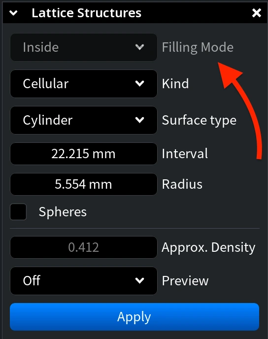
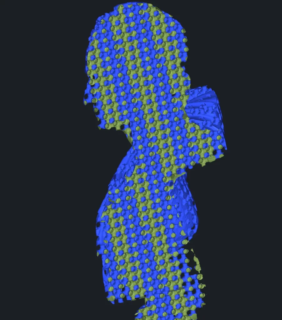
- Cylinder. A lattice made of cylindrical beams connected at nodes. It provides near-uniform mechanical behavior in all directions, making it suitable for general-purpose strengthening and impact-resistant parts.
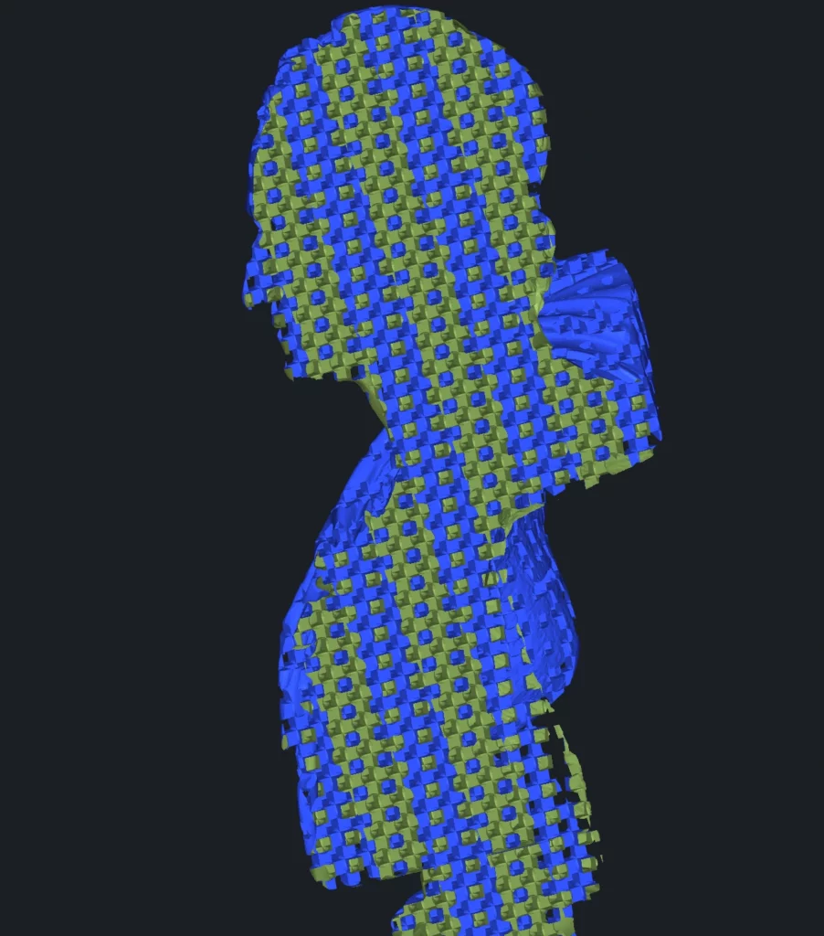
- Rectangle. A lattice made of rectangular beams connected at nodes. Compared to cylinders, it introduces directional stiffness and resists bending more strongly along certain axes.
Other Options with Cellular
Interval (for both Cylinder and Rectangle) defines the spacing between repeating beam cells. Smaller values create a denser reinforcement grid, while larger values produce wider cells and reduce material usage.
Radius (Cylinder) defines the thickness of cylindrical beams. Increasing it strengthens the structure but increases weight and material consumption; decreasing it makes the lattice lighter but less rigid.
Width (Rectangle) defines the thickness of rectangular beams. Increasing it makes the structure stronger and heavier, while decreasing it makes the lattice lighter but less rigid.
Spheres (Cellular only) adds reinforcing nodes at beam intersections. Instead of beams simply meeting at sharp joints, spherical connectors are generated at each junction. This improves load transfer between beams, reduces stress concentration, and increases impact resistance — at the cost of higher material usage and weight.
Sphere Radius controls the size of these connector nodes.
- Larger values create stronger, smoother junctions and better durability but add weight and material consumption.
- Smaller values keep the lattice lighter and more open but reduce joint strength.
The parameters Approx. Density, Components, and Preview behave the same way as in the TPMS mode. Although the internal geometry changes from surface-based to beam-based, these controls keep the same meaning.
By combining different filling modes and lattice types, you can adapt the internal structure of a model to match specific strength, weight, and manufacturing requirements.