The Mesh Cut & Measure tool lets you cut a mesh along a user-defined path and measure its exact length. The tool is located under the Inspect tab.

Once you click on Mesh Cut & Measure, a dedicated panel will open. There, two modes are available:
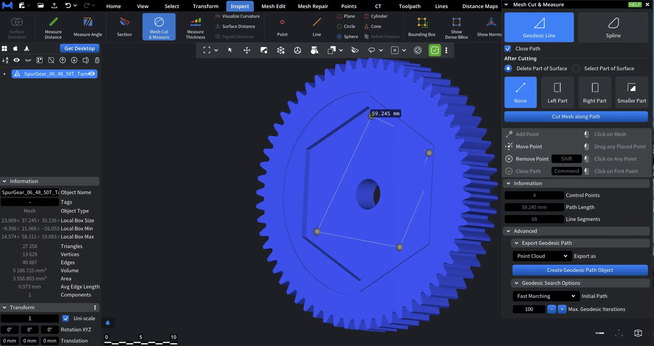
Path Modes
- Geodesic Line creates a path that follows the shortest route along the mesh surface between control points.
- Spline creates a smooth spline curve passing through the user-defined control points.
Close Path determines whether the path is treated as open or closed. When Close Path is disabled, the path remains open. You can continue adding control points, and the cut (or measurement) is based on a single continuous line. When Close Path is enabled, the last control point is automatically connected back to the first one, forming a closed loop.
After Cutting
The After Cutting section defines what happens to the surface regions created by the cut.
Delete Part of Surface. When Delete Part of Surface is enabled, MeshInspector removes surface triangles on the selected side of the cut contour.
You can choose which side to delete using the following options:
-
Left Part deletes the surface on the left side of the contour, relative to the path direction.
-
Right Part deletes the surface on the right side of the contour, relative to the path direction.
-
Smaller Part automatically deletes the smaller of the two surface regions formed by the closed contour.
-
None does not delete any surface. The mesh is split along the contour, and the edges created by the cut are generated and selected, but no surface triangles are removed.
This mode is typically used to trim geometry or create openings by removing part of the mesh.
Select Part of Surface
When Select Part of Surface is enabled, MeshInspector does not modify the geometry.
Instead, it selects surface triangles on one side of the cut contour.
The same side-selection options apply:
-
Left Part selects surface triangles on the left side of the contour.
-
Right Part selects surface triangles on the right side of the contour.
-
Smaller Part selects the smaller of the two surface regions.
-
None does not select any surface region. The mesh is split along the contour, and the edges created by the cut are generated and selected.
This mode is useful for isolating regions for further operations, such as inspection, measurement, coloring, or applying additional tools, without permanently altering the mesh.
Cut Mesh along Path
Cut Mesh along Path applies the currently defined path to the mesh and performs the actual cutting operation.
Information
The Information section provides read-only metrics describing the currently defined path:
- Control Points displays the total number of user-defined control points used to construct the path.
- Path Length shows the total length of the constructed path, measured along the mesh surface.
- Line Segments indicates the number of linear segments used internally to represent the path.
Advanced Settings for Geodesic Line
The Advanced section provides additional controls for exporting the geodesic path and configuring how the path is computed on the mesh surface.
Export Geodesic Path
This section controls how the constructed geodesic path is converted into a scene object.
Export as specifies the type of object created from the geodesic path:
-
Point Cloud creates a new point cloud object containing points sampled along the geodesic path, including surface normals.
-
Polyline creates a new line object representing the geodesic path as connected line segments.
Create Geodesic Path Object creates a new scene object of the selected type using the current geodesic path.
Geodesic Search Options controls how the initial geodesic path is computed before refinement.
-
Initial Path defines the algorithm used to construct the initial approximation of the geodesic path:
-
Fast Marching computes an initial path that is typically closer to the shortest geodesic, but may take longer to calculate.
-
Dijkstra A* uses an A* modification of Dijkstra’s algorithm. Generally fast for near-linear paths, but may be slower when the path deviates significantly from a straight line.
-
Dijkstra bidir. uses a bidirectional version of Dijkstra’s algorithm. Usually fast, but may produce a path that is not the shortest geodesic compared to Fast Marching.
-
-
Max. Geodesic Iterations sets the maximum number of refinement iterations applied to improve the geodesic path after the initial approximation:
-
Higher values may improve path accuracy.
-
Lower values reduce computation time.
-
Advanced Settings for Spline
Spline Options controls how the spline is constructed and refined on the surface.
- Show Geodesic Path as well displays the underlying geodesic path connecting spline control points.
- Max Distance sets the maximum allowed distance between spline points and the geodesic path.
- Add Control Point inserts a new control point at the location where the spline deviates most from the geodesic path.
- Respect Normals forces the spline to remain orthogonal to mesh normals at control points.
- Sampling Step defines the spacing used when inserting additional points between control points.
- Control Stability controls how strongly the spline follows the defined control points.
- Construction Iterations sets the number of refinement iterations used to build the spline.
Export Spline
Export as defines the output type for the spline:
- Point Cloud creates a point cloud representation of the spline.
- Polyline creates a line object representing the spline.
Geodesic Search Options
Here, Spline settings are identical to Geodesic Path.