How to Slice 3D Meshes for 3D Printing with MeshInspector
Most consumer 3D printers feature relatively limited build volumes. These may include:
- 220 x 220 x 250 millimeters;
- 250×210×220 mm;
- 218.88 mm × 122.88 mm × 260 mm, and more.
One way or another, objects that are larger than roughly 250–300 mm per axis frequently require slicing before print. In this situation, MeshInspector is ever-ready to assist you with our ‘Section’ tool to cut the mesh into pieces.
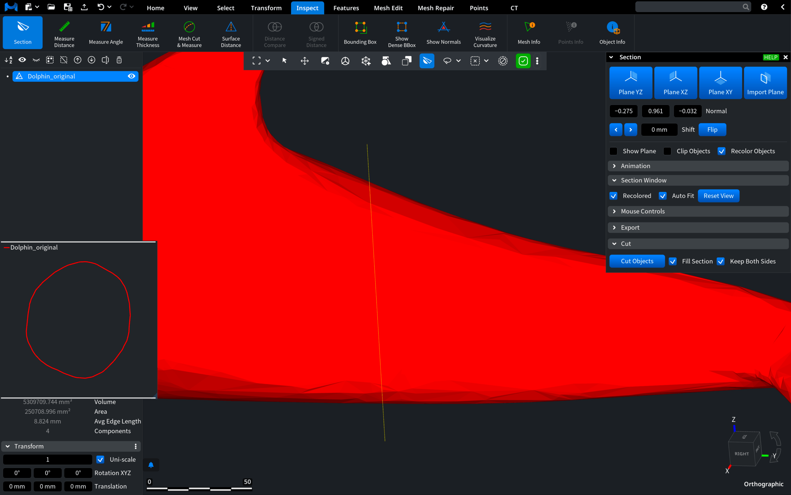
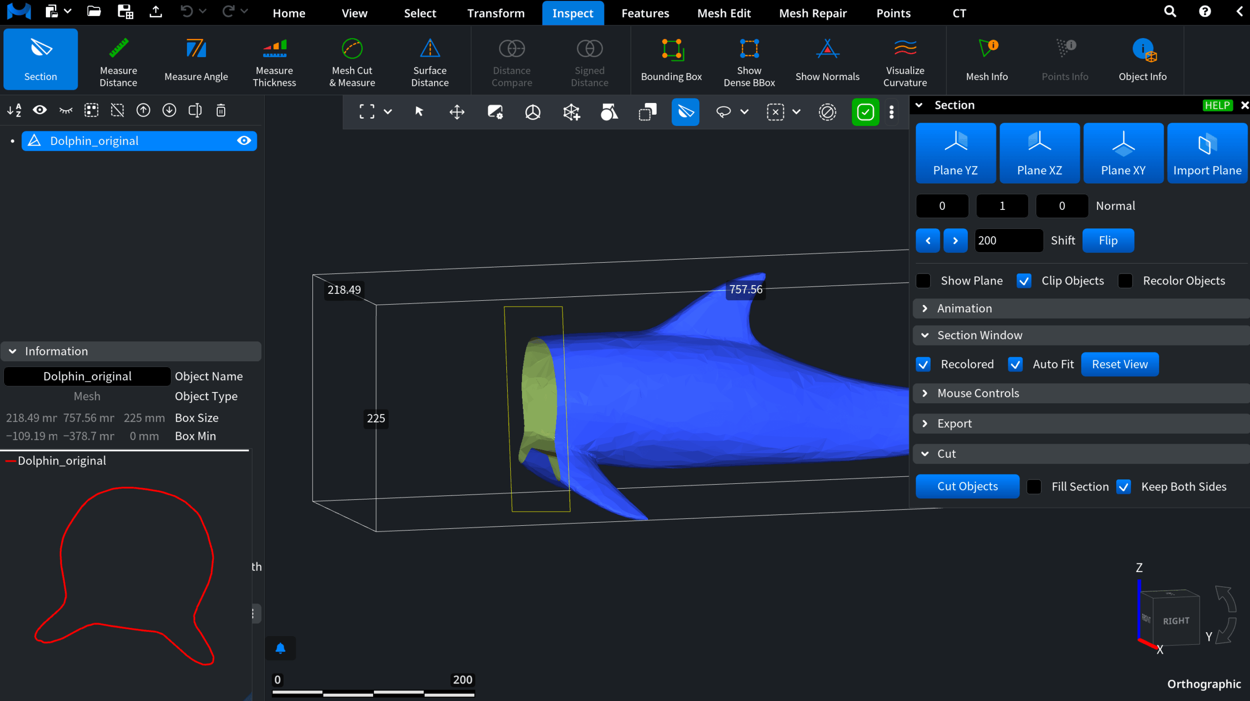
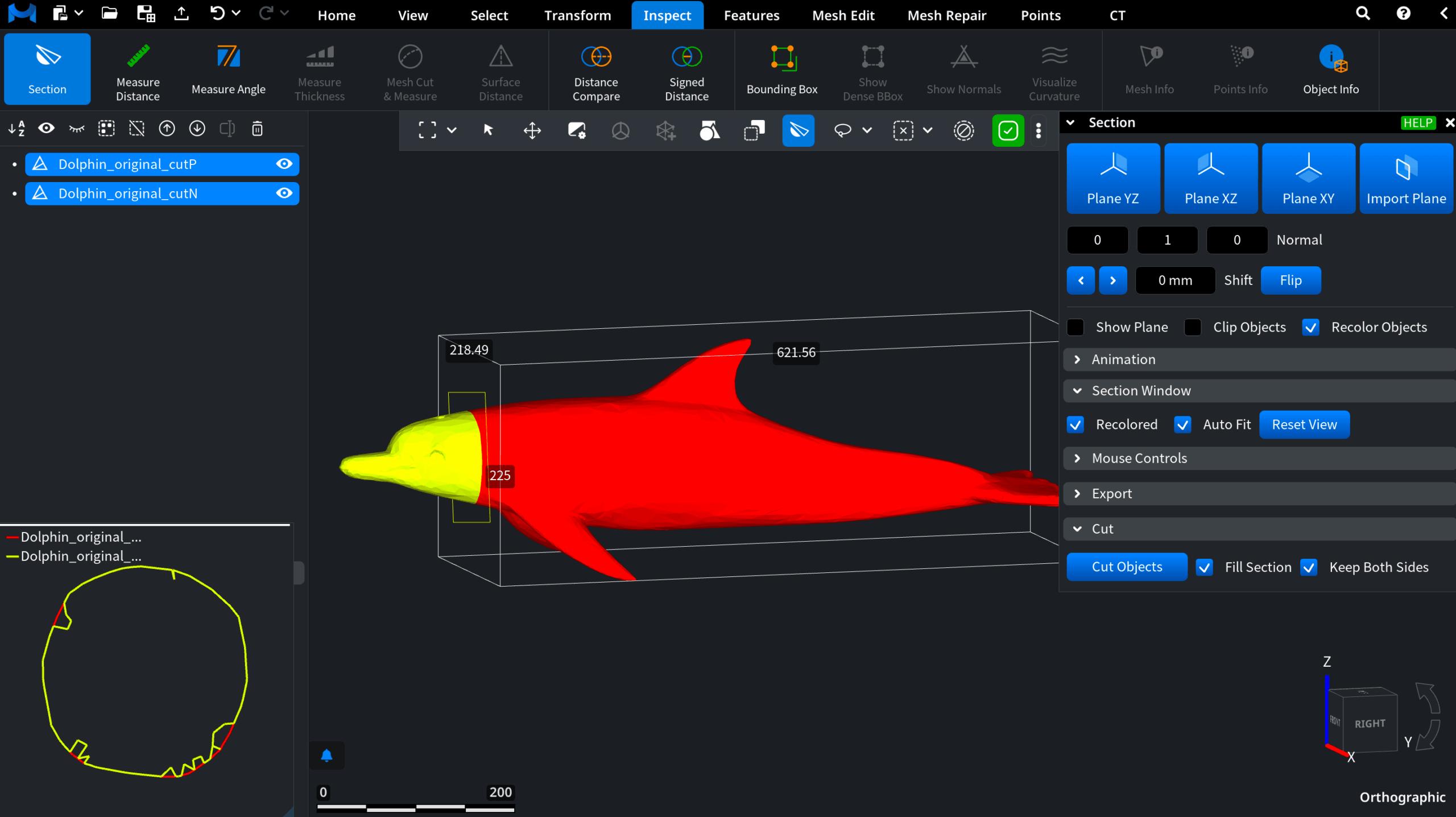
Let’s imagine the following scenario. The model here is a dolphin with its significant dimensions highlighted by the bounding box.
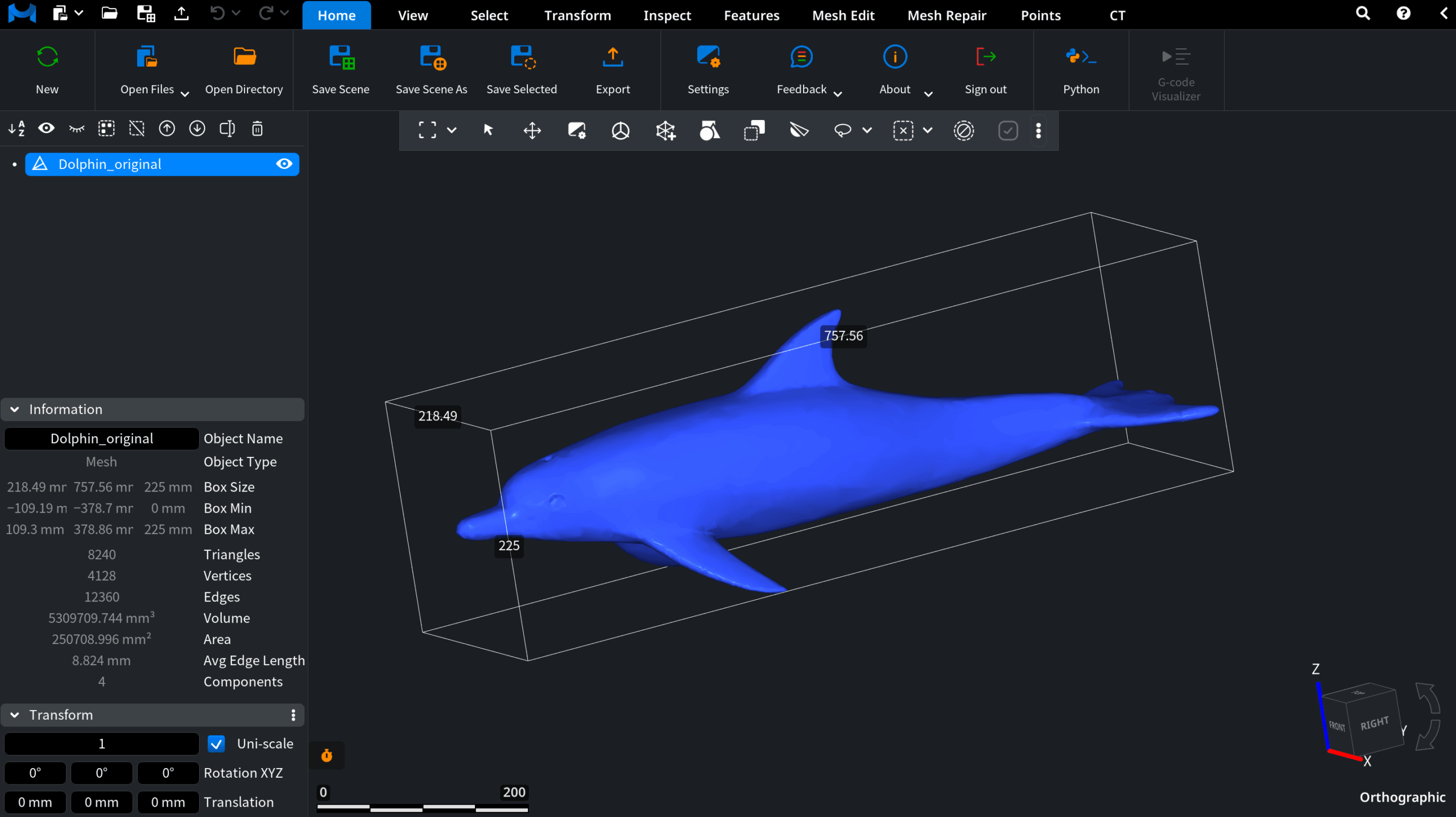
Obviously, its 225 mm height, 218.49 mm width, and 757.56 mm length exceed the typical 3D printing build volumes. Such dimensions will make it impractical to print the object as a single piece.
With MeshInspector, one is free to split a large 3D model for printing, while filling sections along the way.
.
How to Cut Meshes
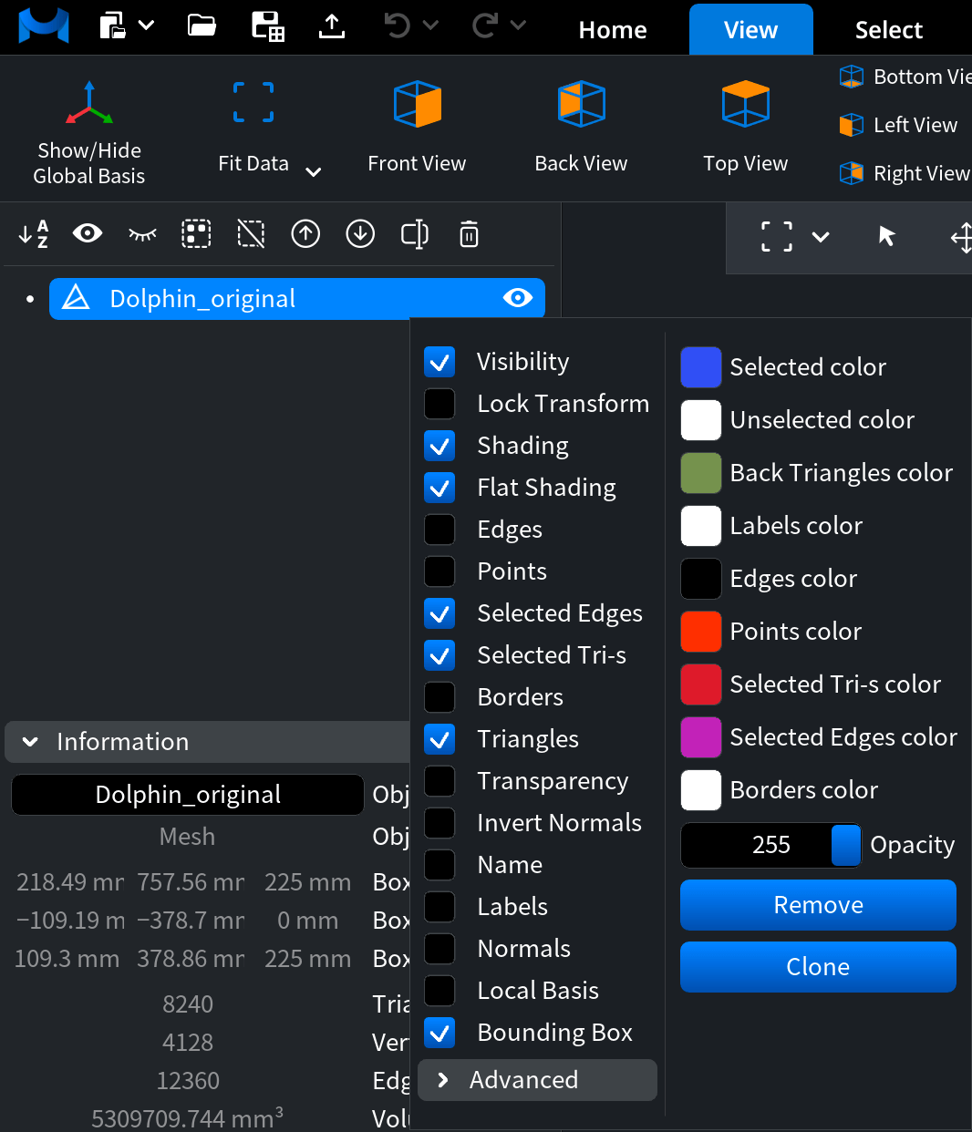
As is shown above, we keep ‘Bounding box’ enabled to check dimensions. On top of that, we toggle ‘Flat shading’ to avoid stitches.
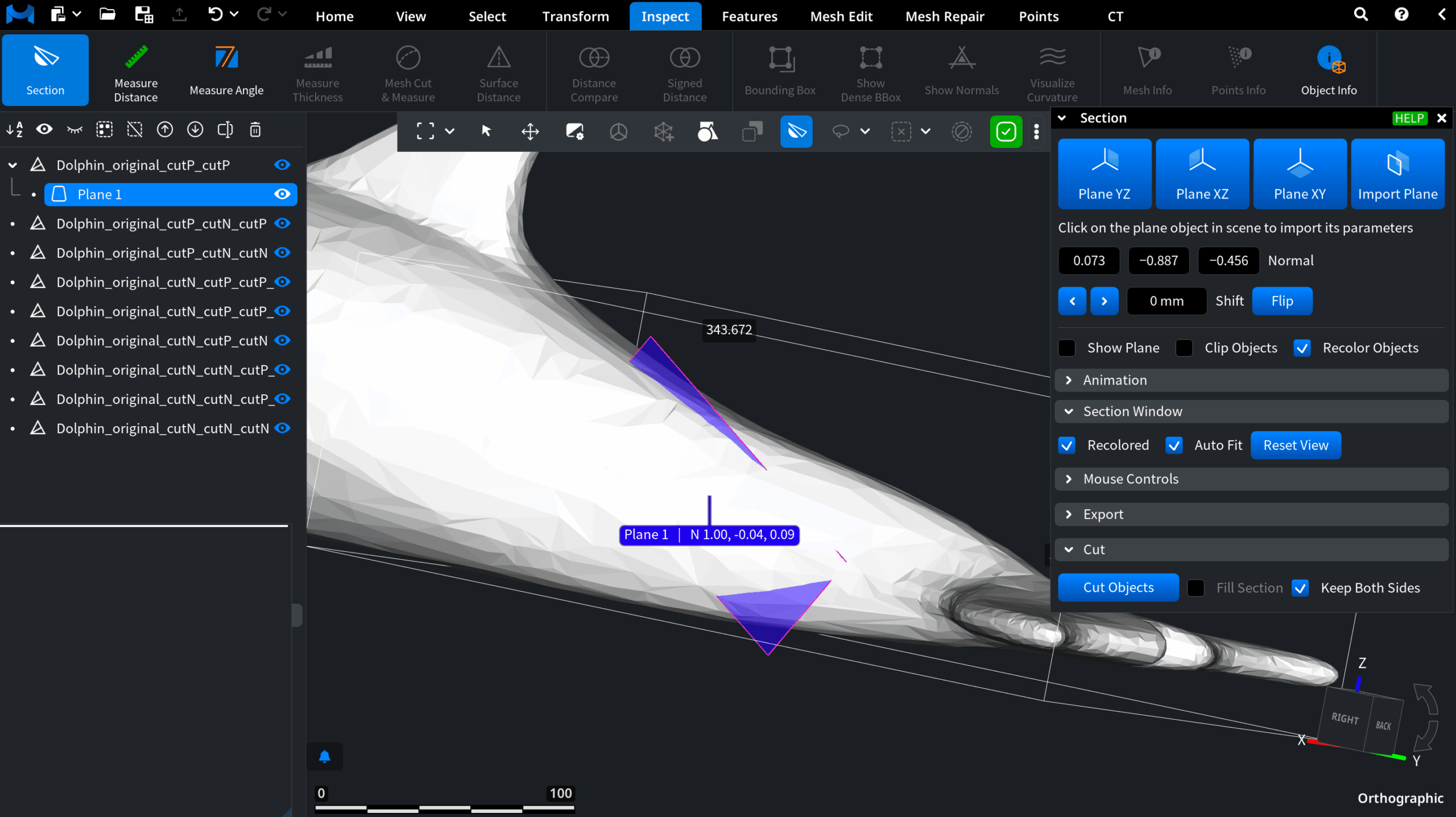
To solve the problem of the oversize model, we open ‘Inspect’ and click ‘Section.’ As shown in the screenshot below, you instantly get three ready-to-use cutting planes.
Three Ready‑to‑Use Cutting Planes
- Plane YZ
- Plane XZ
- Plane XY
These allow you to slice the mesh along the main axes.
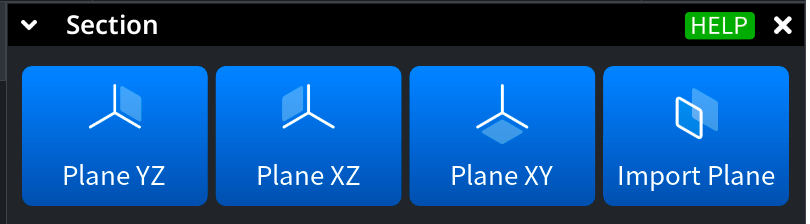
Imported Cutting Plane
As you can see above, there is also a fourth option in place: i.e., our ‘Import Plane’ option for custom previously created orientations.
To create a plane through it, go to ‘Features’ and click on ‘Plane.’

Once the plane is created, it becomes visible in the scene tree.
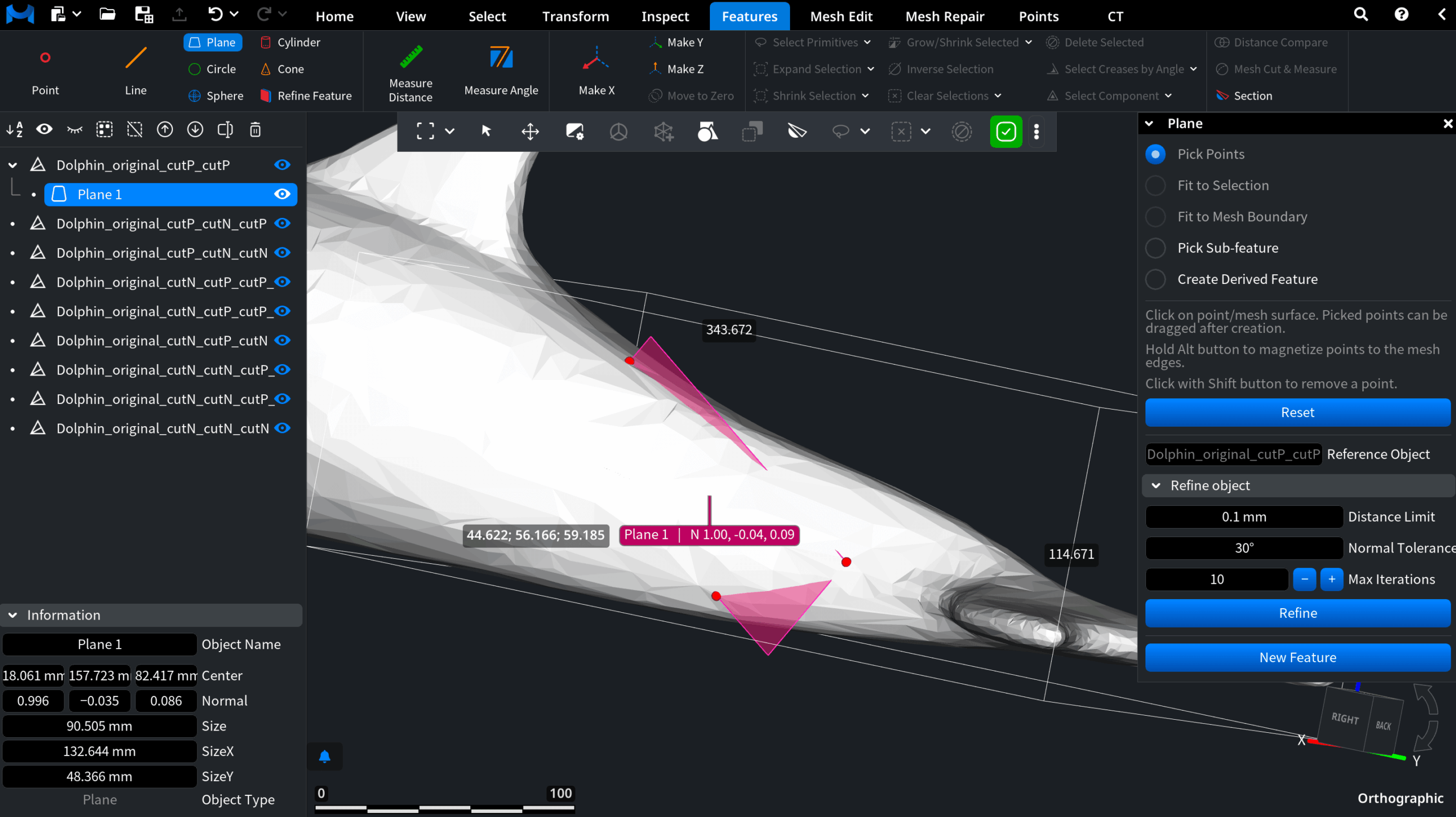
After that, you can return to ‘Section,’ click on ‘Import Plane,’ then choose the plane in the scene tree, and MeshInspector will import all its parameters. All that is left to do is to click on ‘Cut Objects.’
Manually Cut Planes
On top of automatic plane‑based slicing, MeshInspector allows you to draw cutting lines manually. Click anywhere in the scene to place the starting point of a cut. Drag the cursor in the direction of the desired cut, then release to finish drawing the cutting line. After that, you can apply it to cut the mesh, as shown below.
Controlling the Steps
When using the Section tool, MeshInspector lets you precisely control the cutting step — the distance between slicing planes. In our case, we are working on the XZ plane (the orientation cube in the lower‑right corner helps align the model and understand the current axis).
Suppose, we would like to create slices around 200 mm (20 cm) each, which would fit within a standard 3D printer’s build volume. However, at this step size, the section would cut directly through the dolphin’s fin, making our printing operations difficult.
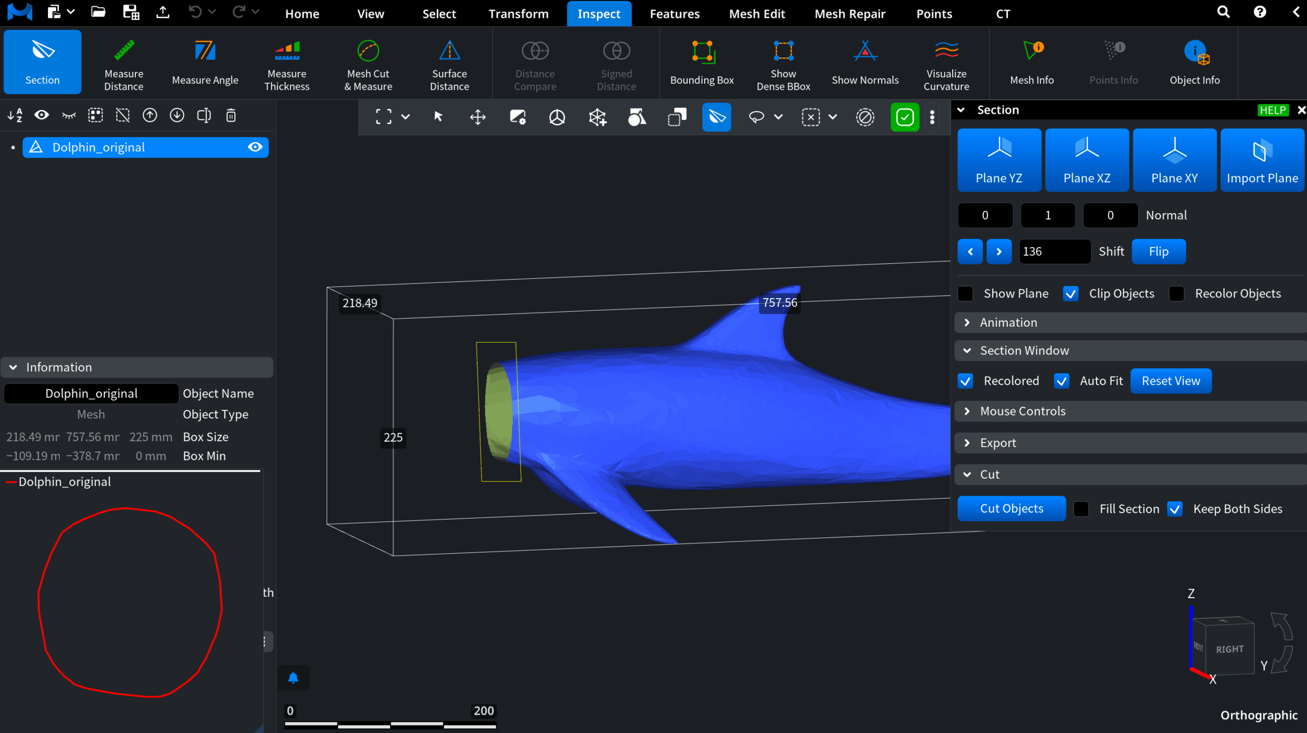
To fix this, we simply adjust the step value in the control panel. MeshInspector allows users to drag the number field or enter a precise measurement. We end up with an optimized 136 mm cutting step. This will avoid damaging the fin while still keeping each segment printable.
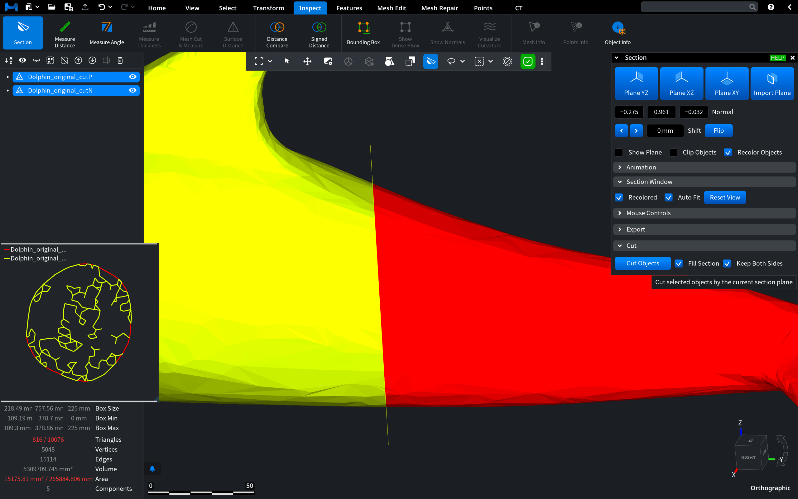
Once the slicing plane is positioned, the next step is to actually apply the cut. This is done with the ’Cut Objects’ button in the ‘Section’ panel. By default, if you click it without any preparation, MeshInspector will simply split the model into two open surfaces. This will leave the cross-sections hollow.
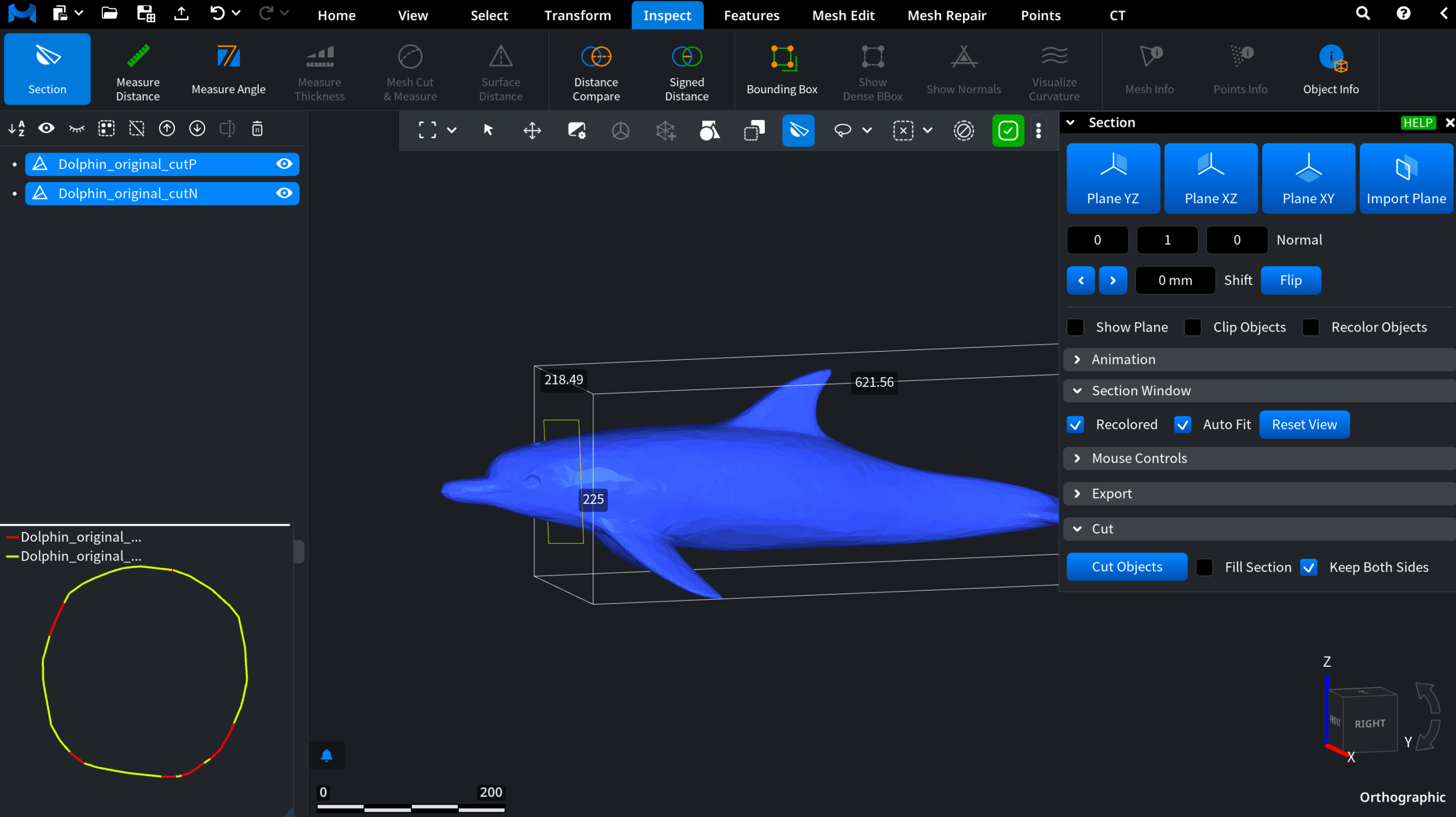
For 3D printing, however, it is important to have closed pieces.
Creating Filled Meshes
To achieve this goal, it is important to prepare the mesh before applying the cut. For that:
- Toggle ’Fill Section,’ so that the sliced areas are automatically closed with new triangles. This will give you filled, solid parts ready for 3D printing;
- At the same time, enabling Recolor Objects assigns different colors to each new mesh. This will make it much easier for you to tell the resulting meshes apart.
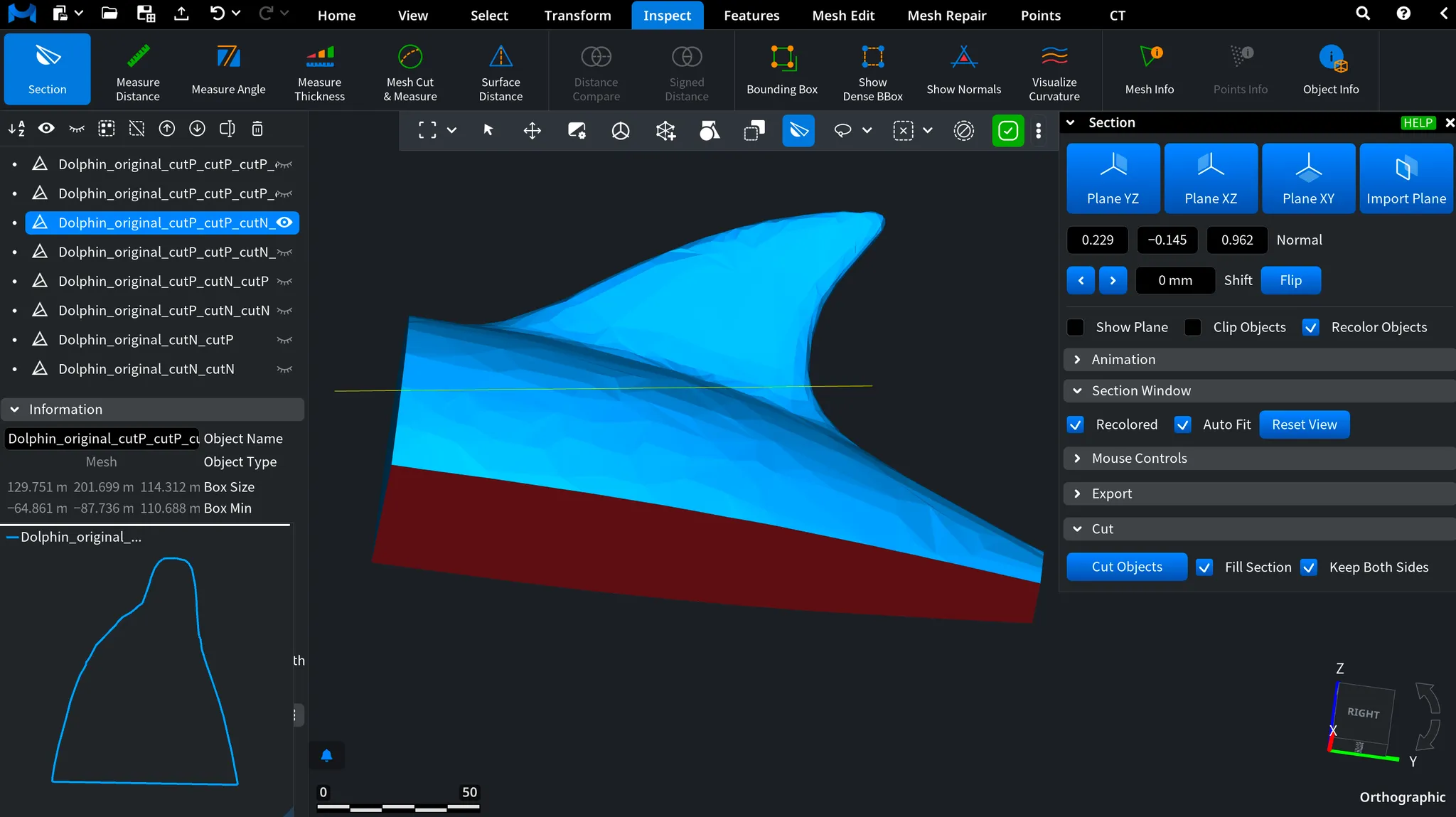
In this fashion, we create three additional segments along the XZ axis and apply a single cut along the XY axis, resulting in a total of eight meshes, as shown below.
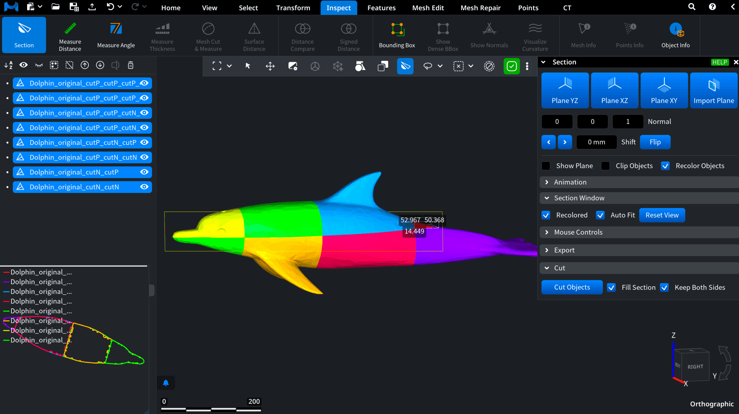
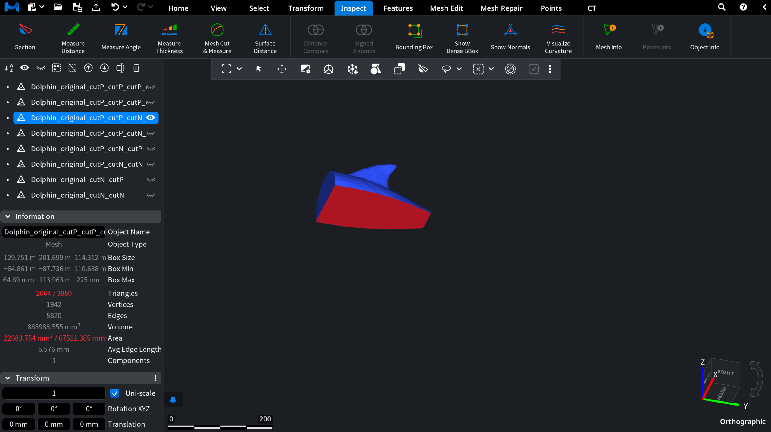
Note that all of them are automatically selected in the scene tree. Our ’Bounding box,’ if already enabled as we did at the start, is automatically applied to the most recent mesh, so that you can instantly verify whether its dimensions fit your printer.
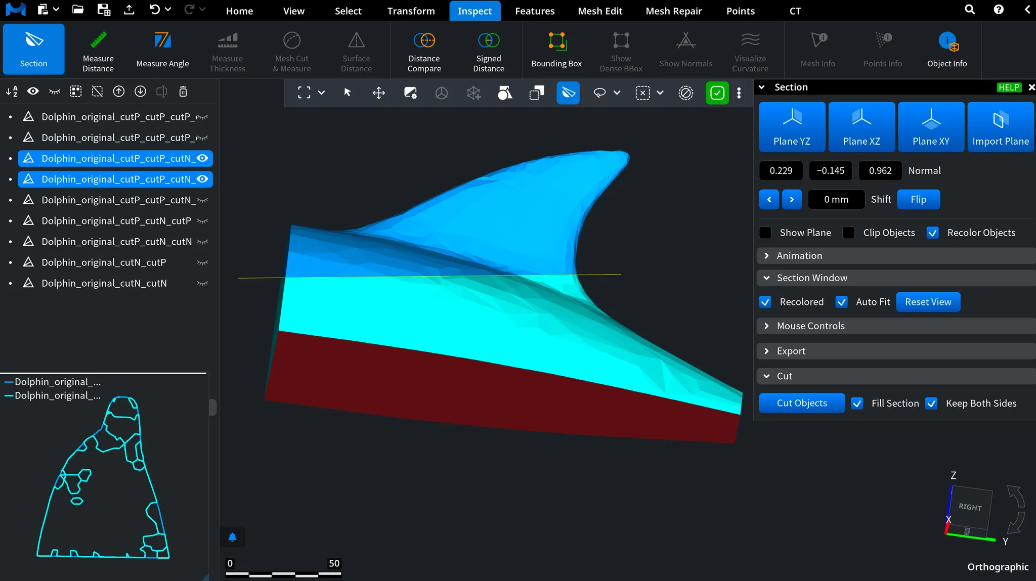
With the F4 shortcut or the arrow controls in the scene tree, you are free to browse through the resulting pieces one at a time. Only the currently selected mesh will be shown. As a result, you are well-positioned to inspect each part individually:
- Red zones mark the areas where new triangles have been generated to fill the cuts;
- Blue zones indicate the original mesh borders.
Connecting the Resulting Parts
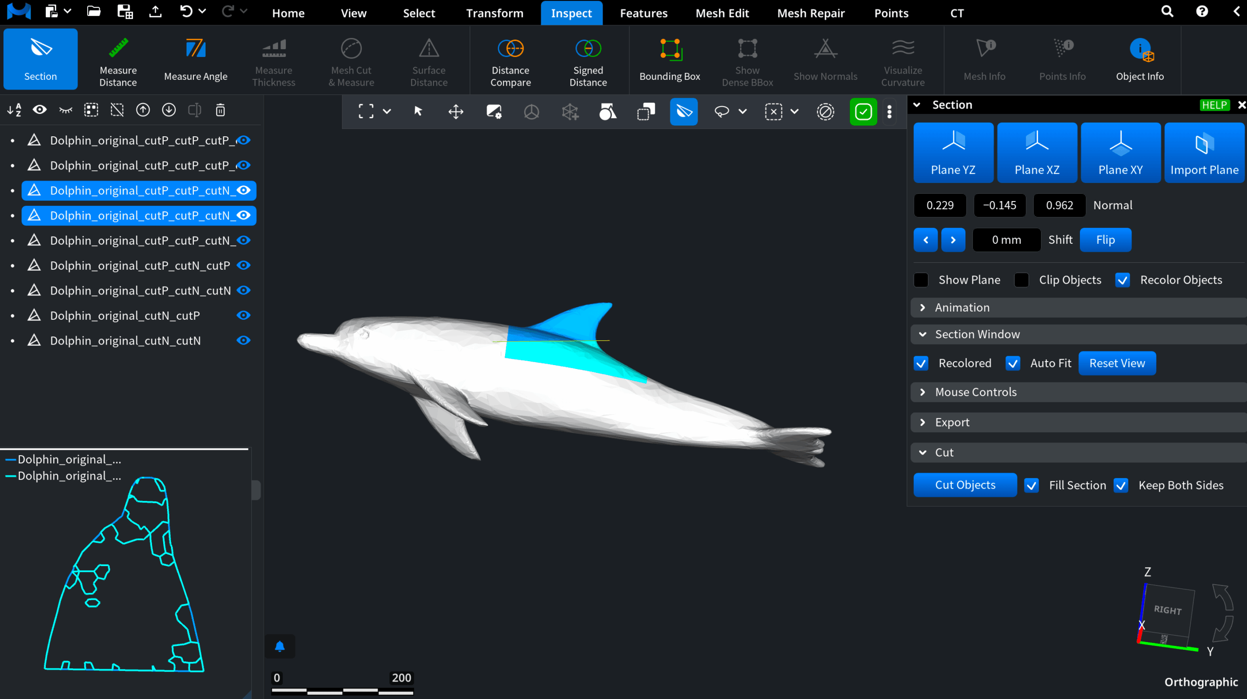
When you are finished, you can bring all the meshes back into view by clicking the eye icon in the scene tree.
Each resulting part can then be prepared for assembly. For this purpose, MeshInspector supports the creation of connectors to join separate pieces together. See our dedicated tutorial for a step-by-step guide: click here to read it.