Loads from YouTube (Google) when you press Play
Imported meshes often contain an irregular triangle distribution. In such meshes, triangle sizes and edge lengths vary significantly across the surface. This uneven topology can make further operations less predictable.
The Remesh tool helps address this issue by rebuilding the surface so that the mesh has nearly uniform edge lengths across the model. As a result, the geometry becomes more evenly distributed, which makes many subsequent mesh editing and repair operations more predictable. To access this tool, open the Mesh Repair tab, then click Remesh to launch the operation.

Remeshing Modes
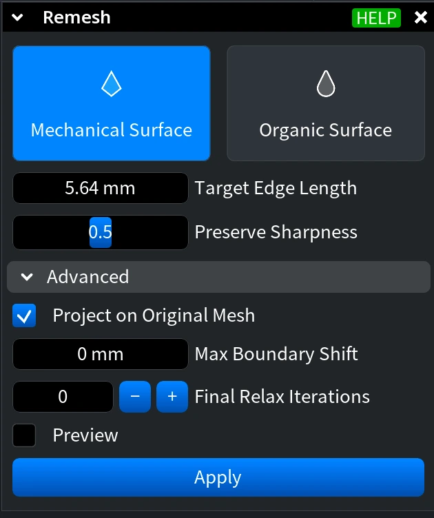
MeshInspector provides two remeshing modes. This setting determines how the remeshing algorithm treats the geometry during the reconstruction process:
- Mechanical Surface works best for non-organic surfaces, e.g., mechanical or CAD models. In such meshes, triangles often have non-uniform shapes, and the surface may contain sharp edges between elements.
- Organic Surface is intended for natural or smooth surfaces. In these meshes, triangles are typically close to equilateral, have similar areas, and the surface does not contain sharp edges.
Settings
Target Edge Length controls the desired length of mesh edges after remeshing. When you activate the Remesh tool for a selected object for the first time, MeshInspector sets this value automatically based on the object’s current average edge length. However, this default value is only a starting point and may not always produce the optimal result.
During remeshing, the algorithm rebuilds the mesh so that most edges become close to the specified value. Smaller values create denser meshes with more triangles and can help preserve finer details, while larger values produce coarser meshes with fewer triangles. Adjust this parameter depending on the required level of detail and the desired density of the resulting mesh.

Preserve Sharpness controls how strongly the algorithm attempts to maintain sharp geometric features during remeshing. Higher values help keep edges and angular transitions more pronounced, while lower values allow the surface to become smoother and more uniform. An edge flip is allowed if it changes the dihedral angle by no more than 30°.
Advanced
Expand the Advanced section to access additional controls that influence how the remeshing operation behaves.
Project on Original Mesh. When this option is enabled, every new vertex created during subdivision is projected onto the original mesh surface before smoothing. This projection applies only to vertices created during subdivision and does not affect vertices moved during other processing stages. This option helps keep the remeshed geometry closer to the original surface.
Max Boundary Shift defines the maximum allowed movement of boundary edges during an edge collapse operation. Increasing the value allows boundary edges to move more freely during remeshing, while smaller values keep the mesh boundaries closer to their original positions.
Final Relax Iterations controls the number of relaxation iterations applied to mesh vertices at the final stage of remeshing. Additional iterations can improve the uniformity of vertex distribution and edge lengths. However, more iterations may cause the resulting mesh to deviate further from the original surface.
When this parameter is set to a value greater than 0, an additional option called No Shrinkage becomes available.
No Shrinkage prevents the surface from shrinking during the relaxation process. When the checkbox is selected, MeshInspector helps prevent shrinkage after multiple relaxation iterations.
Preview, when enabled, updates the mesh appearance in the Viewport in real time as you change the parameters. However, it does not commit the remeshing operation. Because of this, the model properties shown in the Information section remain unchanged during preview and are updated only after you click Apply. For computationally heavy operations, Preview may temporarily freeze the interface.
Click Apply to commit the remeshing operation.
Example: Before
In this example, we apply the Remesh tool to a mechanical model. This is why Mechanical Surface is selected: the model contains triangles with non-uniform shapes and sharp edges between surface elements.
Pay attention to the Target Edge Length parameter. Again, when the Remesh tool is activated for a selected object for the first time, this value is set automatically based on the object’s current Average Edge Length. However, the automatically set value is only a starting point and may need to be adjusted depending on the desired result.
Here, we deliberately set a lower Target Edge Length value to make the resulting mesh denser and avoid noticeable distortion of the original geometry.
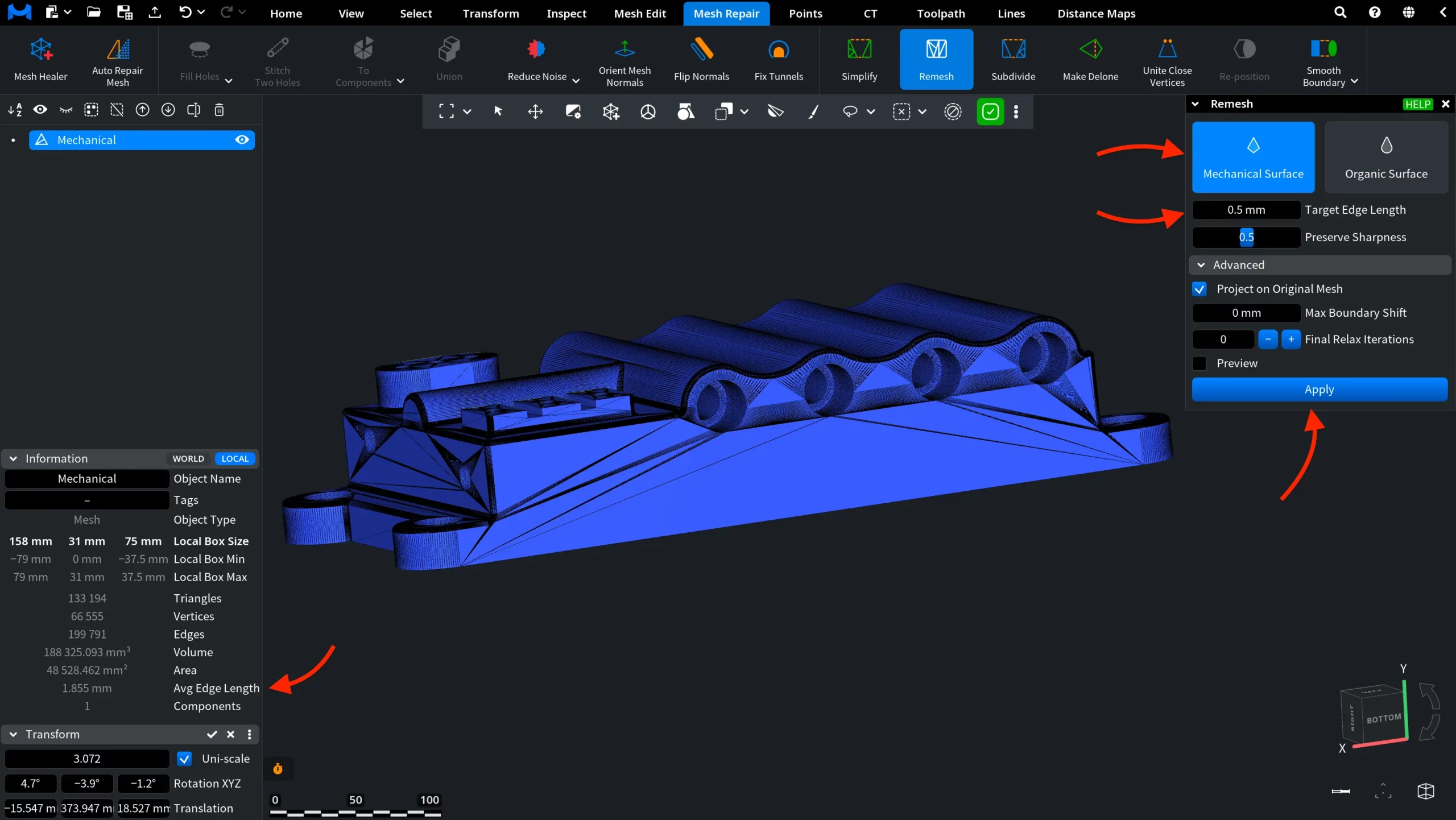
Other settings are left at their default values.
Also, for better visibility, we pressed L to visualize the triangles and activated Flat Shading.
We click Apply to launch the remeshing operation.
Example: After
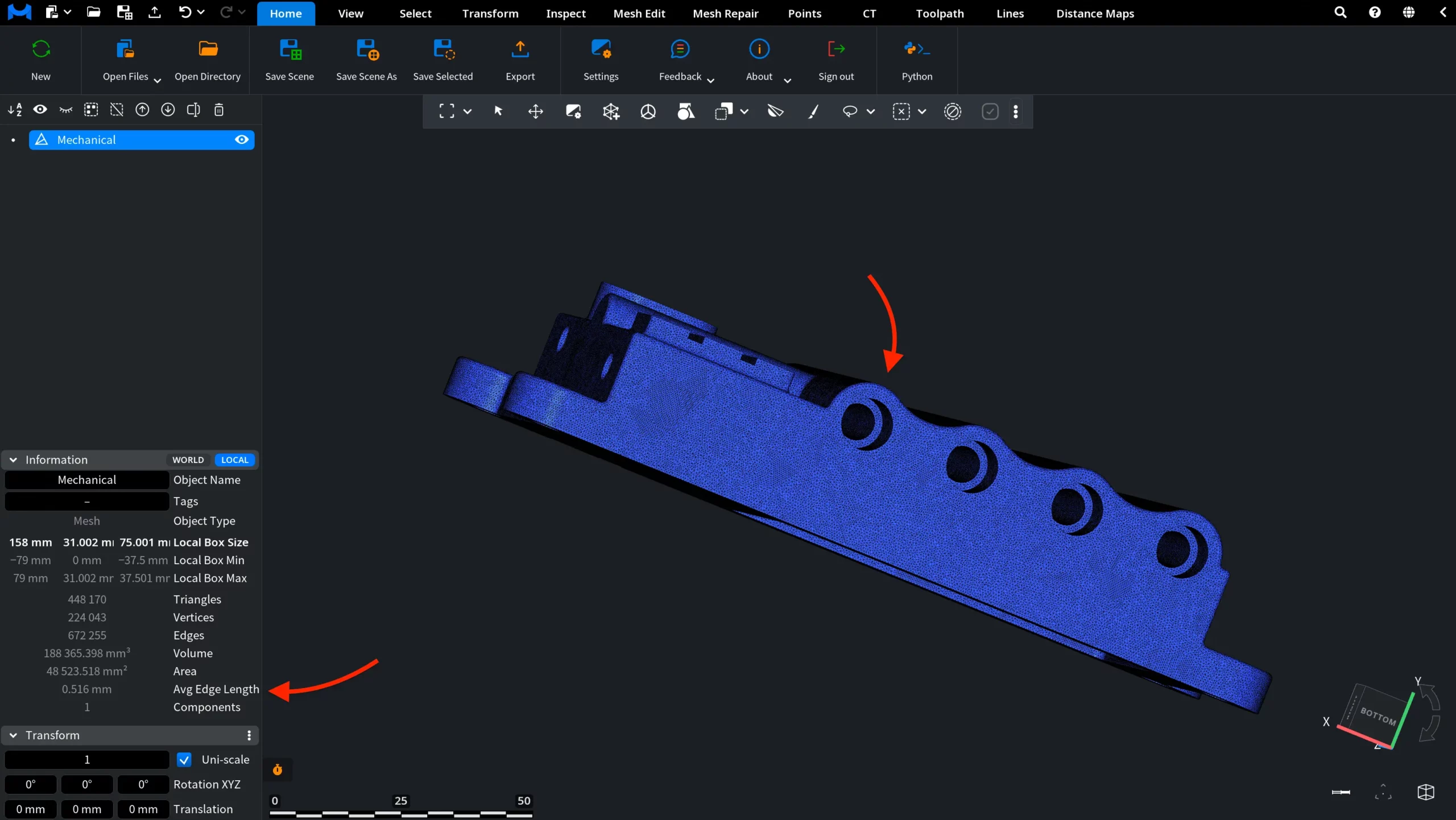
After applying Remesh, the mesh is rebuilt with a more uniform edge-length distribution, based on our settings. The triangles across the surface become more consistent in size and shape, resulting in a more regular mesh structure while preserving the overall geometry of the model.
How the Remesh Tool Works