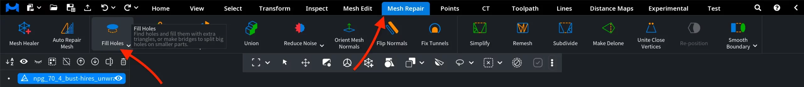
Mesh integrity is of paramount importance. To address this, MeshInspector offers a dedicated Fill Holes tool that you can find under the Mesh Repair tab. It detects open boundaries (i.e., holes) in the mesh and closes them by generating new geometry. This can be done:
- By filling the opening with additional triangles
- By creating bridges that split a large hole into smaller parts (making it easier to close and control the result)
After you click Fill Holes, a dedicated panel opens, allowing you to tune three potential operations:
- Fill Single
- Fill All
- Make Bridge
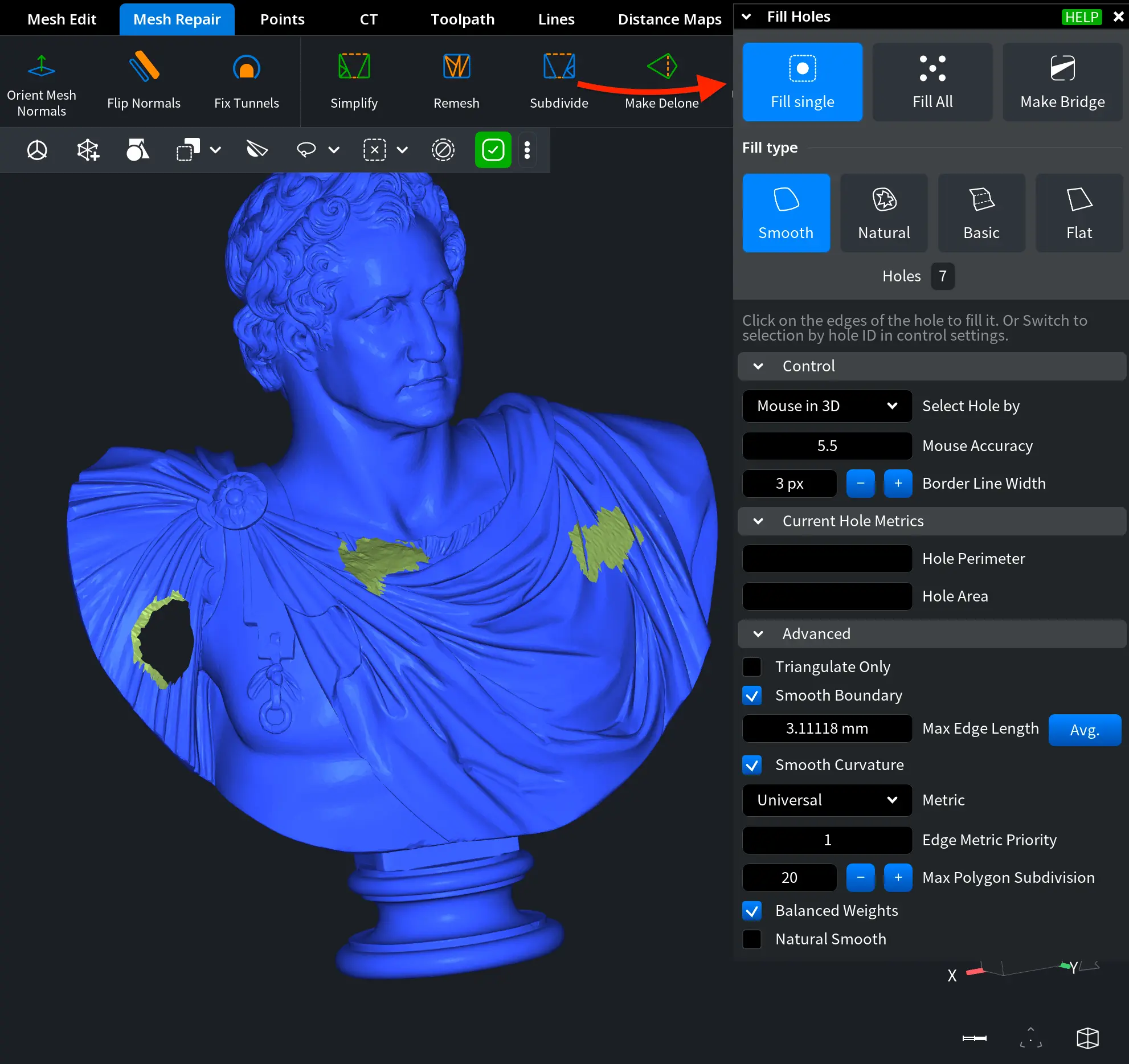
Fill Single
Fill Single allows you to focus on a single hole that can be selected by clicking the edge of the hole or by entering the Hole ID.
Fill Types
The Fill Type defines how MeshInspector constructs the patch that closes the opening. Four filling strategies are available:
- Smooth generates a smooth surface that blends with the surrounding geometry. It attempts to create a continuous transition between the new triangles and the existing mesh surface, making the repair less noticeable.
- Natural generates a smooth surface and adjusts the surrounding edges to better preserve the natural shape of the model. During the operation, the tool may expand and reposition nearby vertices to maintain the overall curvature of the surface.
- Basic fills the hole with a flat surface using more detailed triangulation. The higher triangle density allows the patch to adapt better to complex hole boundaries.
- Flat fills the hole with a simple flat surface using the minimal number of triangles required to close the opening.
Below the Fill Type options, the number of currently detected holes is shown.
Settings
Control
Control allows you to define how you select holes for repair. You can either click directly on the edges of a hole in the viewport or switch to selection by Hole ID in the control settings.
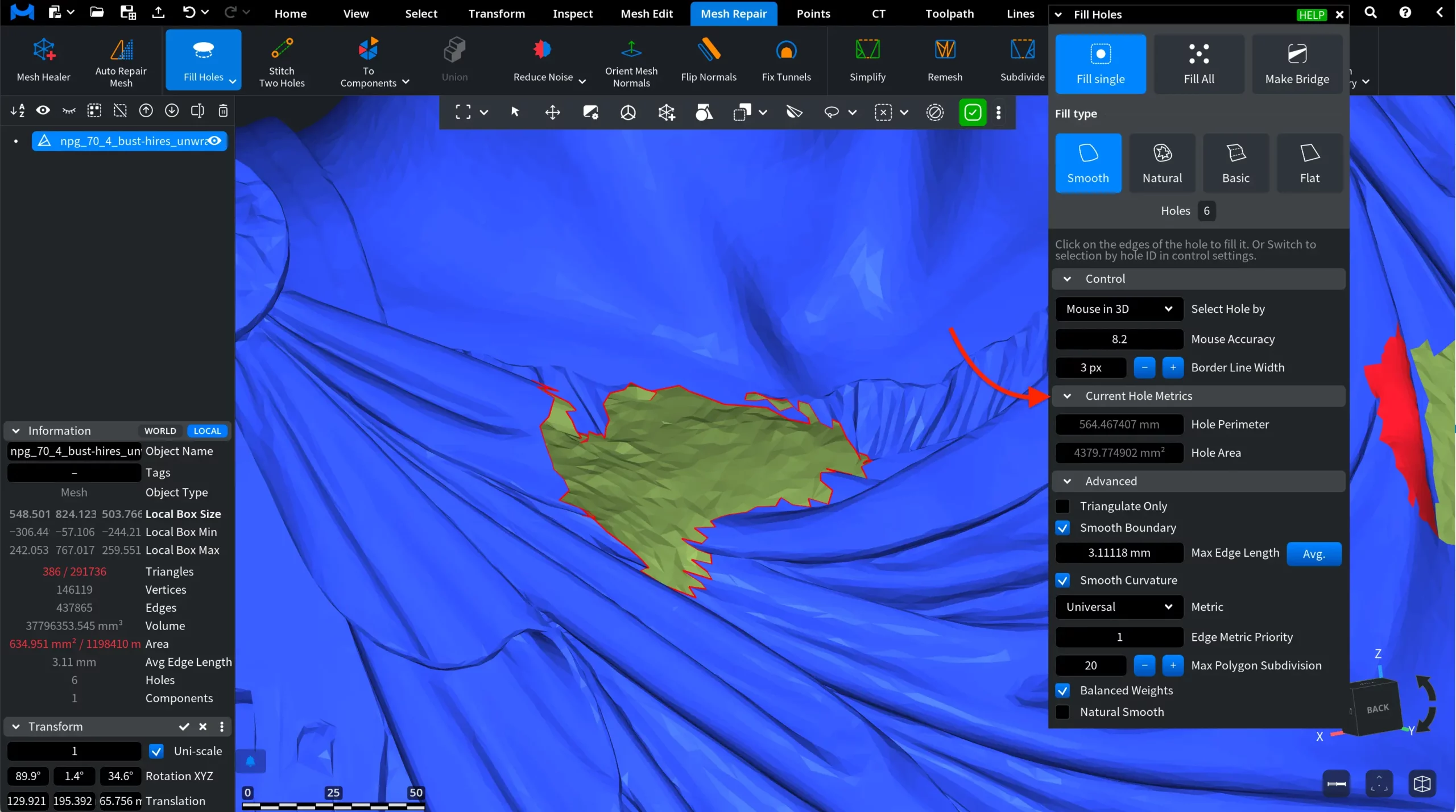
Mouse in 3D, when enabled, provides you with the following controls:
- Mouse Accuracy defines how precisely the tool detects the hole edge when selecting it in the viewport. Higher values increase the detection tolerance, making it easier to select holes on complex or dense meshes.
- Border Line Width controls the visual thickness of the highlighted hole boundary in the viewport. Increasing this value makes the edge outline more visible, which may be helpful when working with detailed geometry or small openings.
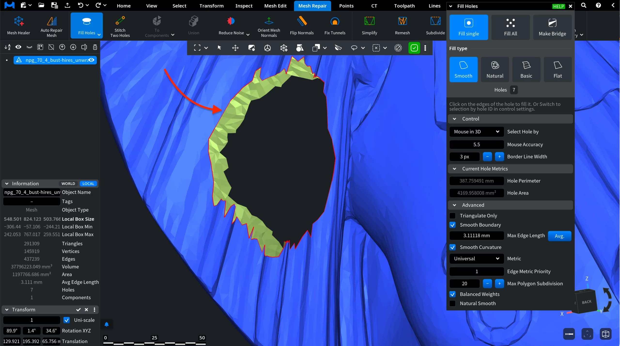
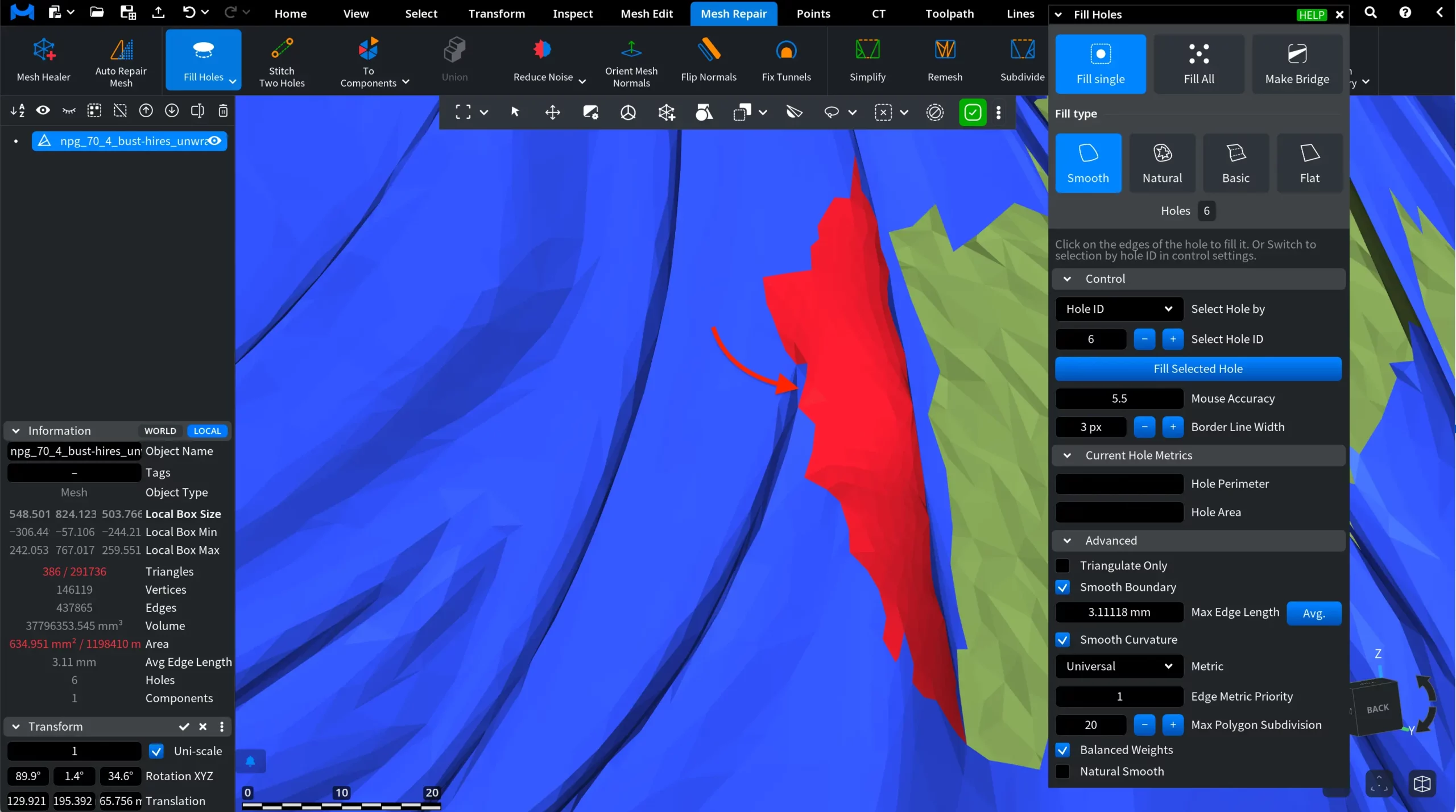
In this mode, you need to hover the cursor over the edge of the hole. The hole edge will then be highlighted in red.
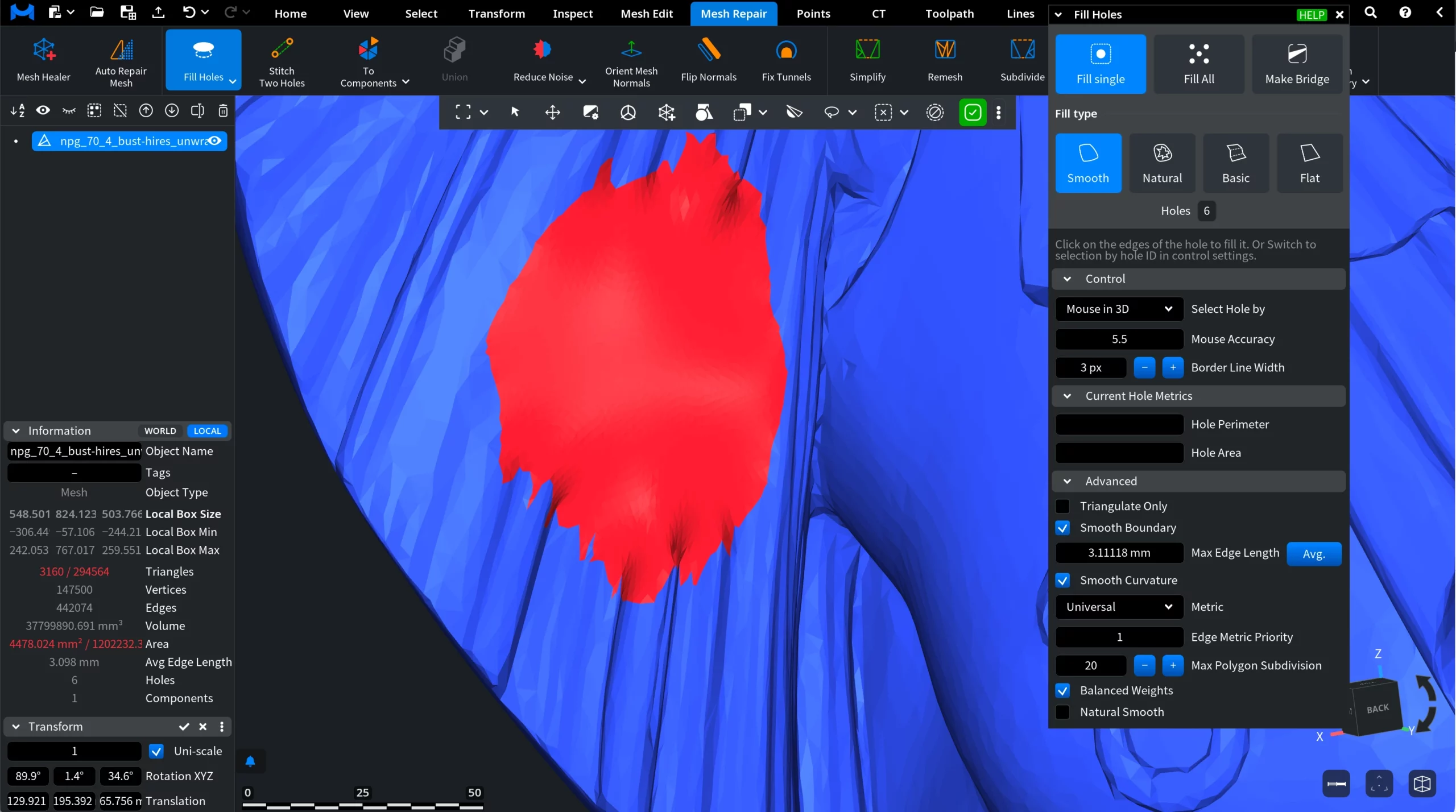
Then click to fill the hole. MeshInspector will generate a surface patch according to the selected Fill Type, closing the opening.
Select Hole ID, when chosen, allows you to select a hole using its numerical identifier instead of selecting it directly in the viewport. You can enter the ID manually or use the plus and minus buttons to switch between detected holes.
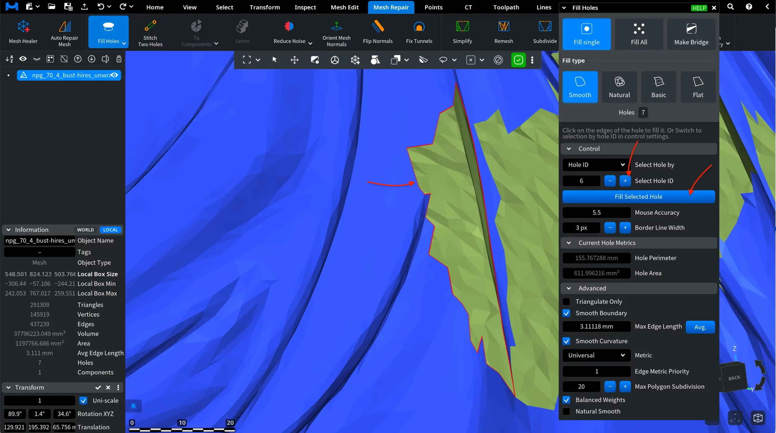
After the desired hole is selected, click Fill Selected Hole to apply the filling operation according to the chosen Fill Type. Note that Border Line Width works the same, while Mouse Accuracy becomes inactive. You can still change its value, but hovering over the edge will no longer trigger hole detection.
Current Hole Metrics
Regardless of which Control mode is active, once you select a hole, i.e., either by hovering the cursor over its edge or by entering its ID, the Current Hole Metrics section displays the following information:
- Hole Perimeter. The total length of the boundary that forms the hole.
- Hole Area. The estimated surface area of the opening.
Advanced
Depending on the selected Fill Type, different Advanced settings will be available so you can fine-tune the result.
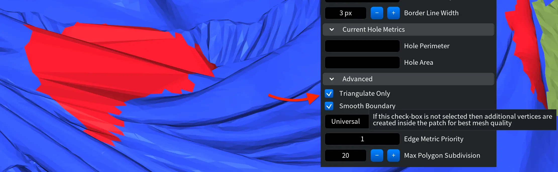
Triangulate Only. When Triangulate Only is enabled, MeshInspector fills the hole using a simple triangulated patch without generating additional vertices inside the patch. If this option is disabled, the tool may introduce additional internal vertices during the filling process to improve mesh quality and produce a smoother result. When Triangulate Only is enabled, several smoothing-related parameters become unavailable, and the patch is generated using a simpler triangulation strategy.
Smooth Boundary. When Smooth Boundary is enabled, MeshInspector smooths the angle between the triangles of the generated patch and the surrounding mesh. This helps create a smoother transition between the filled area and the existing surface.
Max Edge Length controls the subdivision of the generated patch. Patch mesh subdivision stops once all edges are shorter than the specified value.
Avg. automatically sets the value based on the average edge length of the mesh.
Smooth Curvature. When Smooth Curvature is enabled, MeshInspector attempts to produce a smoother surface across the generated patch. This option helps reduce visible discontinuities between triangles and creates a more uniform surface.
Metric defines the optimization criterion used during hole filling. It determines how the triangulation of the patch is evaluated and improved. Several metric options are available:
- Universal. A general-purpose metric that produces good results in most situations. It minimizes both the diameter of the circumscribed circle around each triangle and the dihedral angle between adjacent triangles.
- Planar is designed for holes that lie on or near a plane. This metric minimizes the sum of circumcircle radius multiplied by the triangle aspect ratio and penalizes triangles whose normals point away from the hole plane.
- Complex is optimized for more irregular or geometrically complex holes where preserving stable triangulation is important.
- Min Area minimizes the total area of the surface patch used to fill the hole. This option works best when the hole has a degenerate shape or when the surrounding triangles are degenerate.
Edge Metric Priority controls the relative importance of edge-related optimization compared to triangle-related optimization during triangulation.
- 0 means the edge component of the metric is completely ignored.
- 1 represents the default balanced behavior.
- Higher values increase the importance of edge-related metrics relative to triangle quality.
Adjusting this parameter allows you to influence whether the triangulation prioritizes edge structure or overall triangle quality.
Max Polygon Subdivision defines the maximum number of subdivision steps that can be applied when generating the patch mesh. Each subdivision splits a triangle into smaller polygons to improve mesh quality. Increasing this value allows the algorithm to perform more refinement steps, which can produce a smoother and more detailed patch but may increase processing time.
Balanced Weights. When Balanced Weights is enabled, the algorithm uses weight values recommended in academic literature when performing smooth vertex positioning. If this option is disabled, unit weights are used instead. Unit weights are more tolerant of degenerate configurations but may produce slightly less balanced smoothing results.
Natural Smooth. When Natural Smooth is enabled, the algorithm expands and repositions edges around the patch in order to better preserve the natural shape of the surrounding surface. This option helps the filled region blend more naturally with the original geometry, especially when repairing complex or irregular holes.
Fill All
The Fill All operation repairs all detected holes in the mesh at once using the selected Fill Type and current parameter settings, while allowing you to exclude specific holes from the operation.
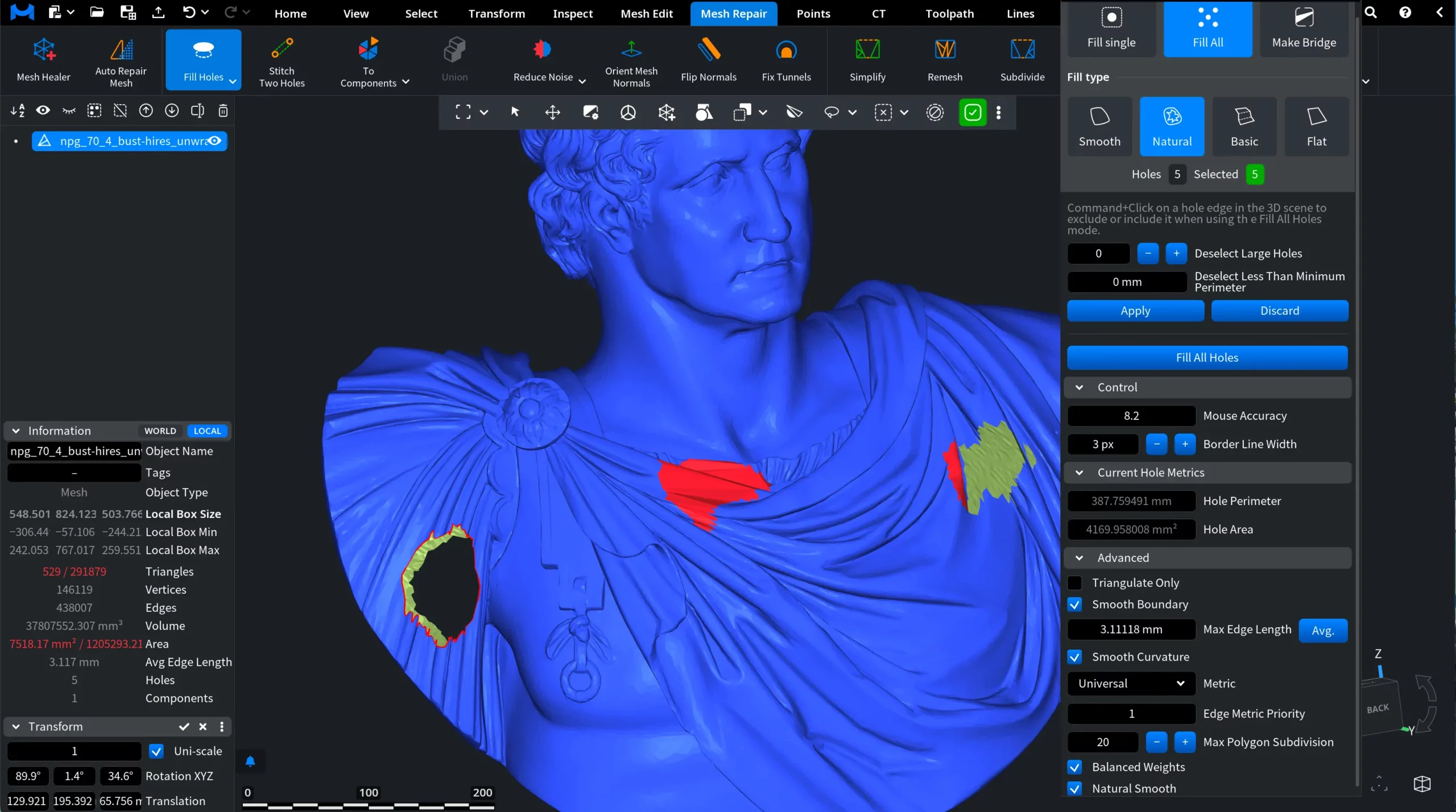
At the top of the panel, MeshInspector displays the number of detected holes and the number of currently Selected holes that will be processed. By default, all detected holes are selected for repair. However, you can manually include or exclude individual holes before applying the operation.
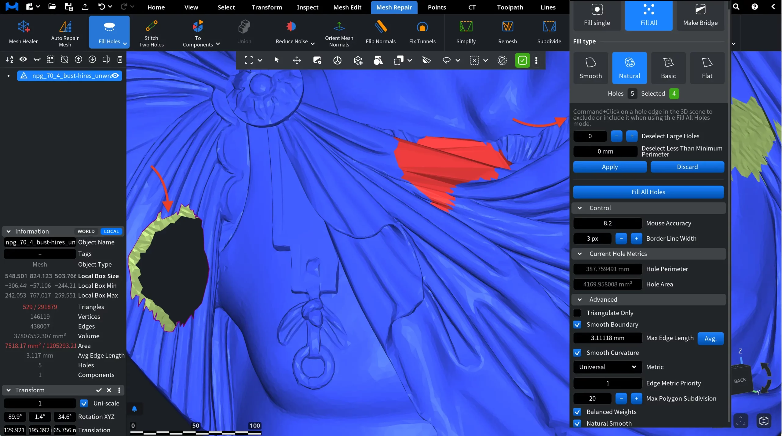
To do this, hold Command and click on a hole edge in the viewport.
- Red edges indicate holes that are currently selected and will be filled.
- Dark red edges indicate holes that have been excluded from the operation.
When a hole is excluded, the Selected counter in the panel updates accordingly, as shown in the screenshot below.
Automatic Hole Filtering
You can also exclude holes automatically using the filtering options provided:
- Deselect Large Holes removes the specified number of holes with the largest perimeter from the current selection.
- Deselect Less Than Minimum Perimeter excludes holes whose perimeter is smaller than the specified threshold.
Applying the Selection
After configuring the selection:
- Apply confirms the filtering settings.
- Discard resets the selection changes.
In all other respects, the settings are the same as in Fill Single.
Make Bridge
The Make Bridge operation allows you to connect two open hole edges by generating a surface between them.
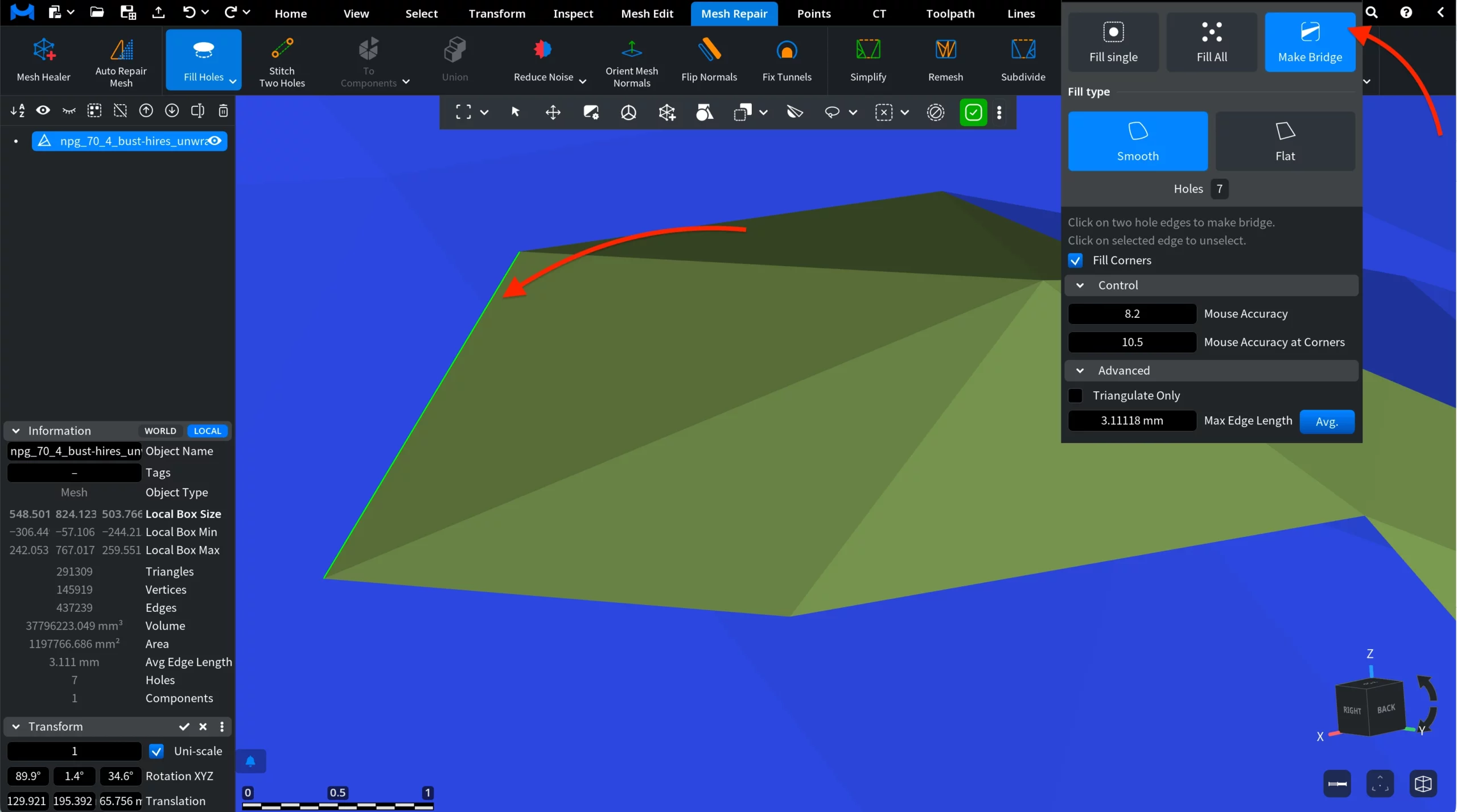
Then click two hole edges in the viewport. These edges define the boundaries that will be connected. The first selected edge becomes green. If necessary, click it again to remove it from the selection. Then hover over the second edge (highlighted in red) and click it.
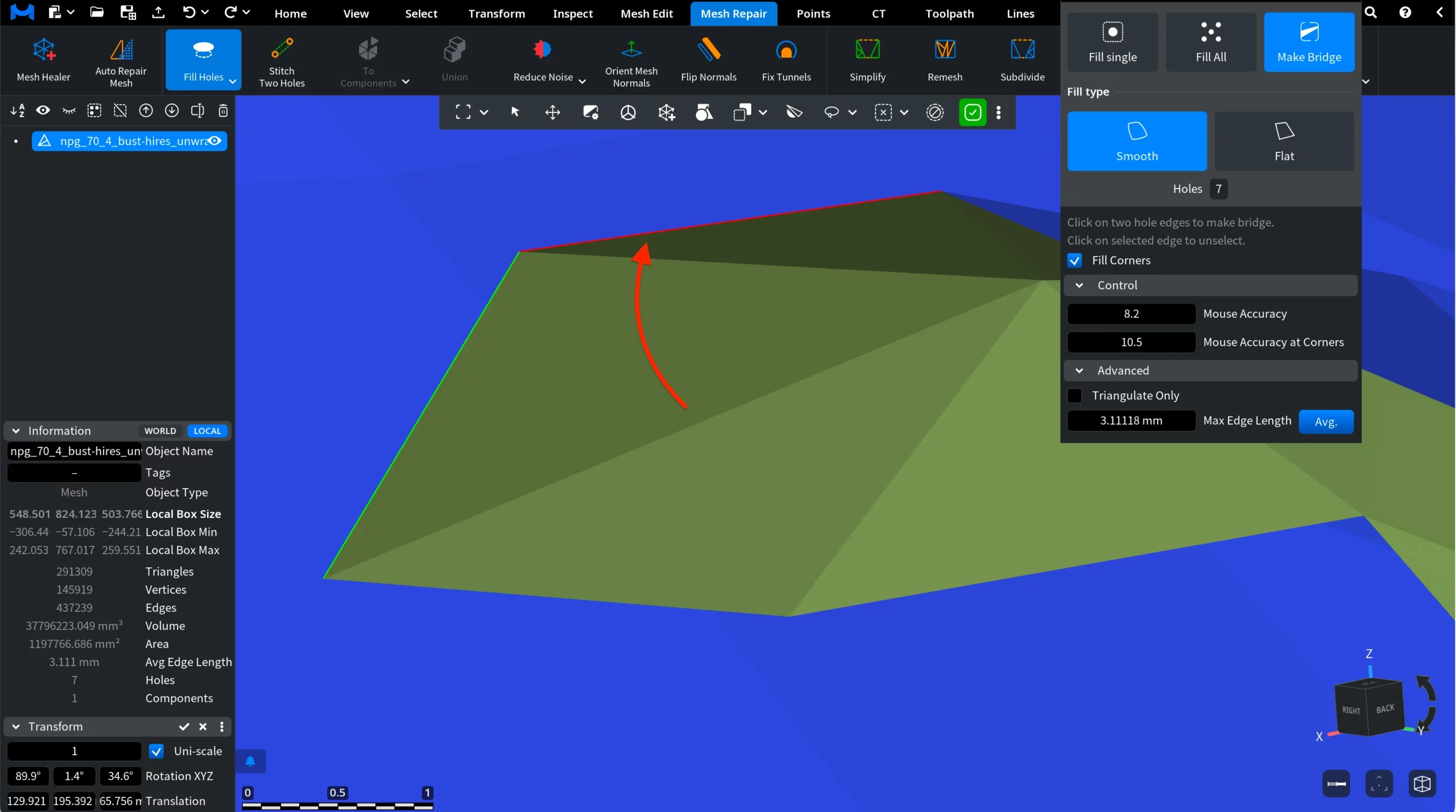
The bridge will be created after the second click.
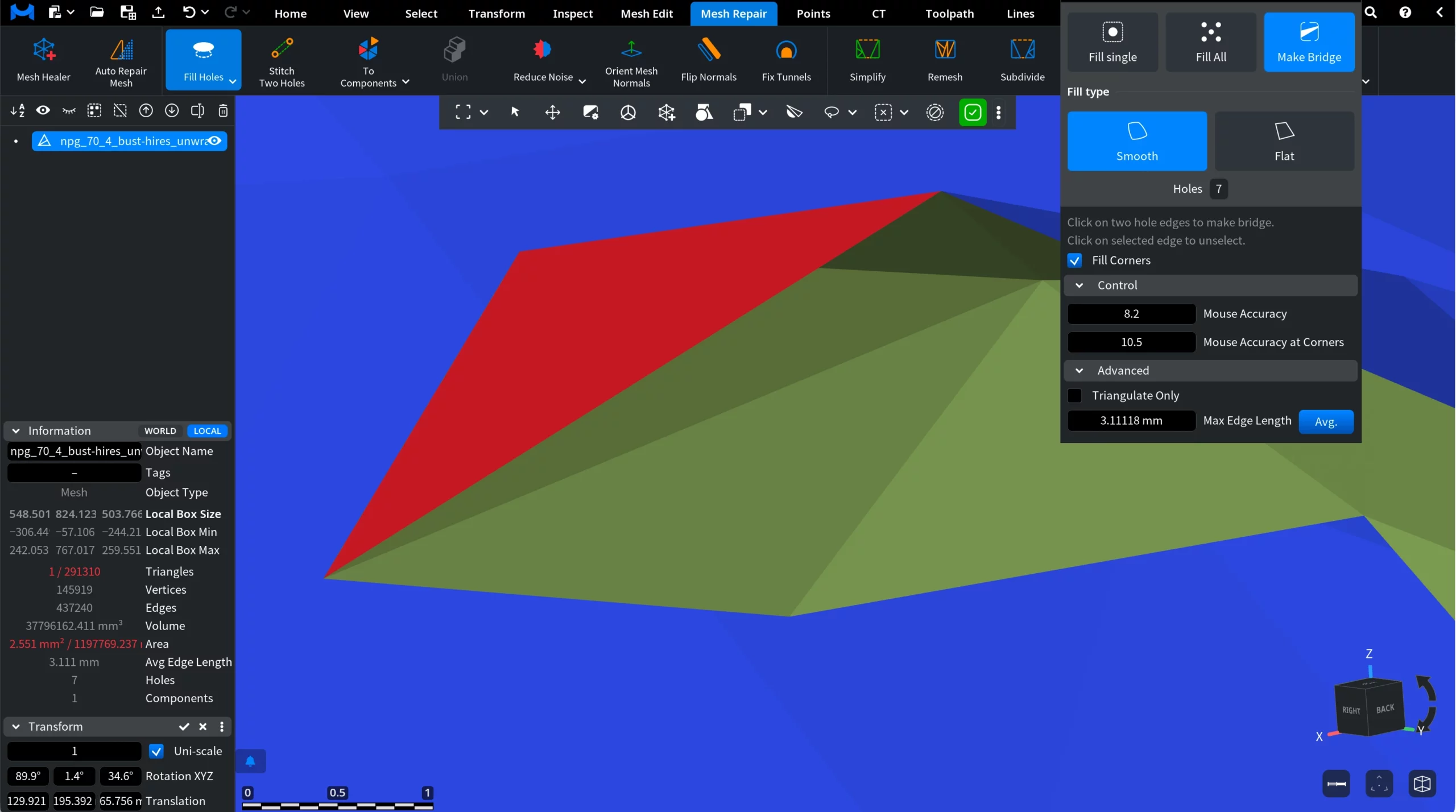
Fill Type
The Fill Type setting defines how the bridging surface is generated:
- Smooth creates a surface that smoothly interpolates between the two boundaries, producing a more organic transition.
- Flat generates a simpler planar-style triangulation between the boundaries.
Fill Corners
The Fill Corners option helps handle irregular or sharp boundary regions by inserting additional triangles near corners to improve stability of the generated surface.
Control
The Control section determines how accurately hole edges are detected when selecting boundaries.
- Mouse Accuracy defines how close the cursor must be to a boundary edge for it to be highlighted and selected.
- Mouse Accuracy at Corners controls the detection sensitivity specifically near sharp boundary corners.
- Higher values make it easier to select edges, while lower values require more precise cursor placement.
Advanced
The Advanced settings provide additional control over the generated bridge:
- Triangulate Only, when enabled, fills the bridge area using simple triangulation without applying smoothing adjustments.
- Max Edge Length limits the maximum length of triangles created during bridge generation, helping maintain consistent mesh density. Patch mesh subdivision stops when all mesh edges are shorter than this value.
- Avg. automatically computes the average edge length of the mesh and uses it as the Max Edge Length value.