The Stitch Two Holes tool connects two open boundaries in a mesh by generating a triangulated surface between them. This operation is useful when two holes belong to the same broken region of a surface.
Unlike Fill Holes, which closes boundaries independently, Stitch Two Holes reconstructs the missing surface between them. In cases like the one shown below, using Fill Holes would produce a large patch that seals the gap instead of restoring the original geometry.
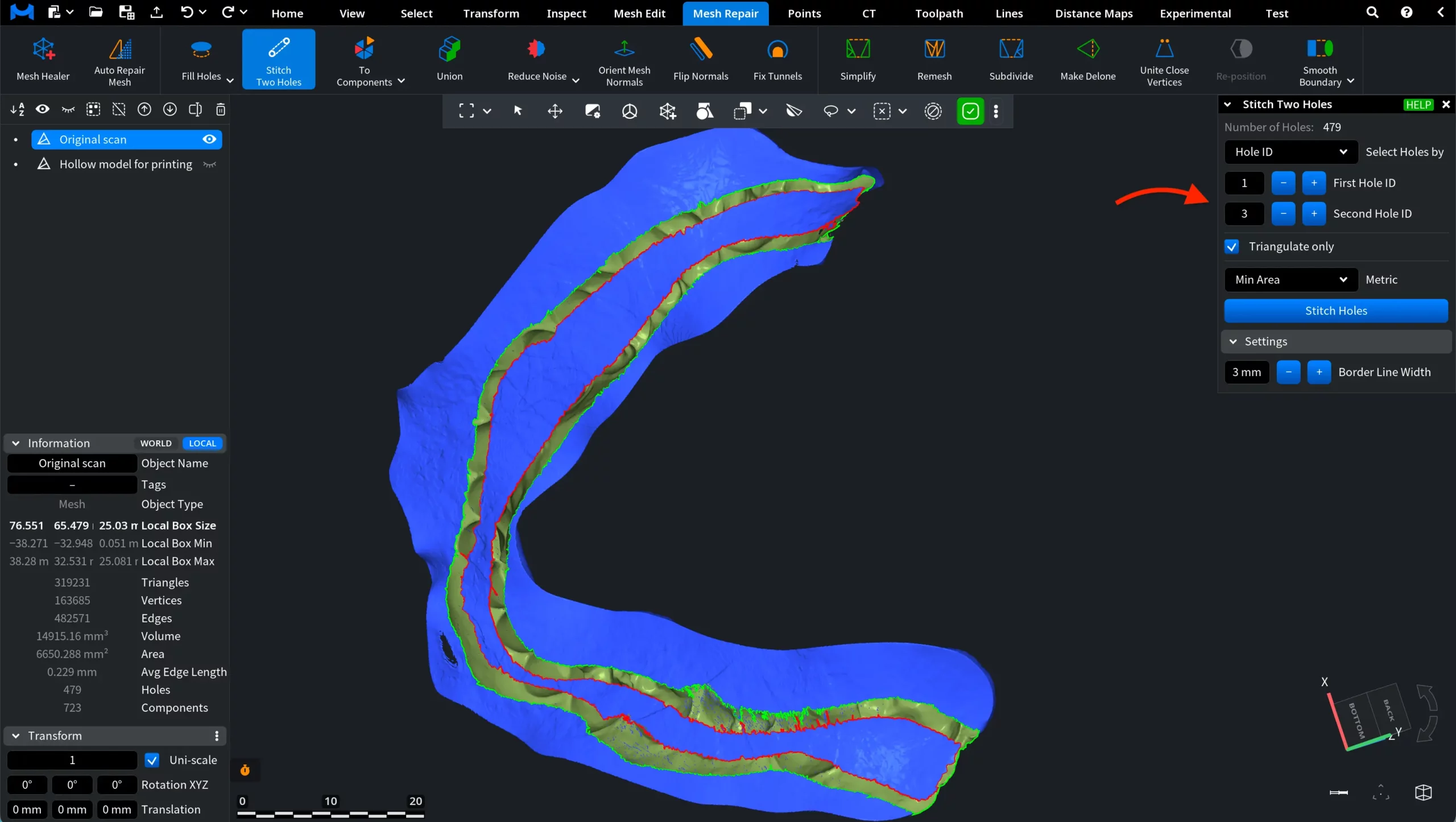
To use the tool, go to the Mesh Repair tab and click Stitch Two Holes.

Fill Holes vs. Stitch Two Holes
In the screenshot below, the mesh contains two long open boundaries that belong to the same broken region of the surface. These boundaries form a single missing strip of geometry.
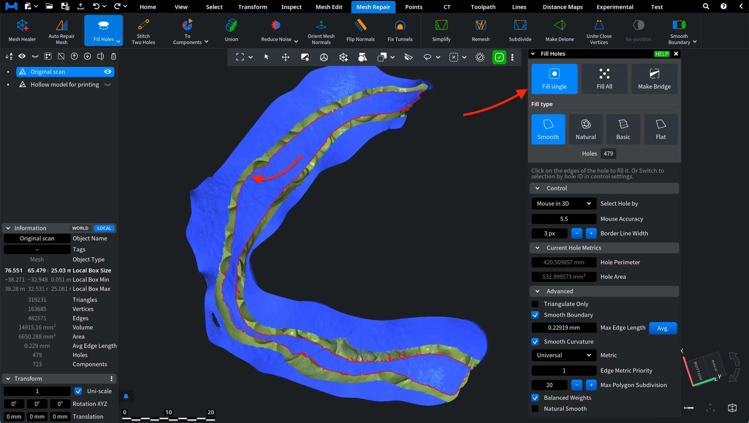
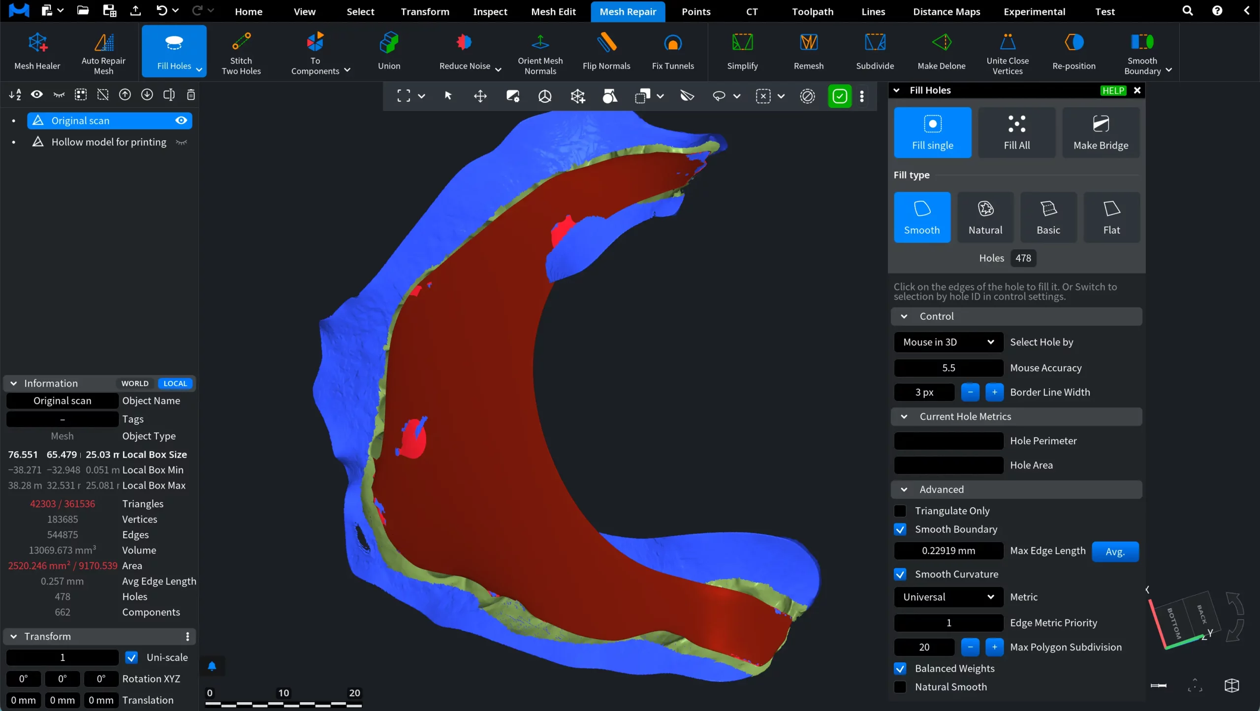
When the Fill Holes tool is applied, it does not produce the desired result. Instead, Fill Holes treats the opening as a single hole and fills it with a surface patch. Because the gap extends along the entire model, this operation seals the interior of the mesh rather than reconstructing the missing surface between the two boundaries. The same behavior is observed when using both Fill Single and Fill All modes.
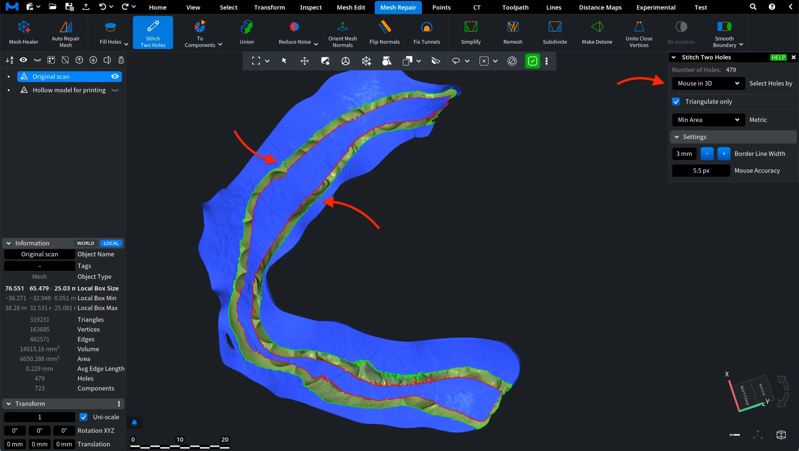
In this case, it is better to use Stitch Two Holes. Once activated, a dedicated panel appears on the right. With the default Mouse in 3D mode, click the first hole boundary: it becomes highlighted in green. Then hover over the second boundary: it is previewed in red. Clicking the second boundary immediately starts the stitching operation.
After selecting both boundaries, the Stitch Two Holes tool generates a triangulated surface between them, effectively stitching the gap.
In this case, instead of sealing the entire opening with a single patch, the mesh is reconstructed along the missing strip. The resulting surface follows the shape of the original geometry, preserving continuity between the two sides.
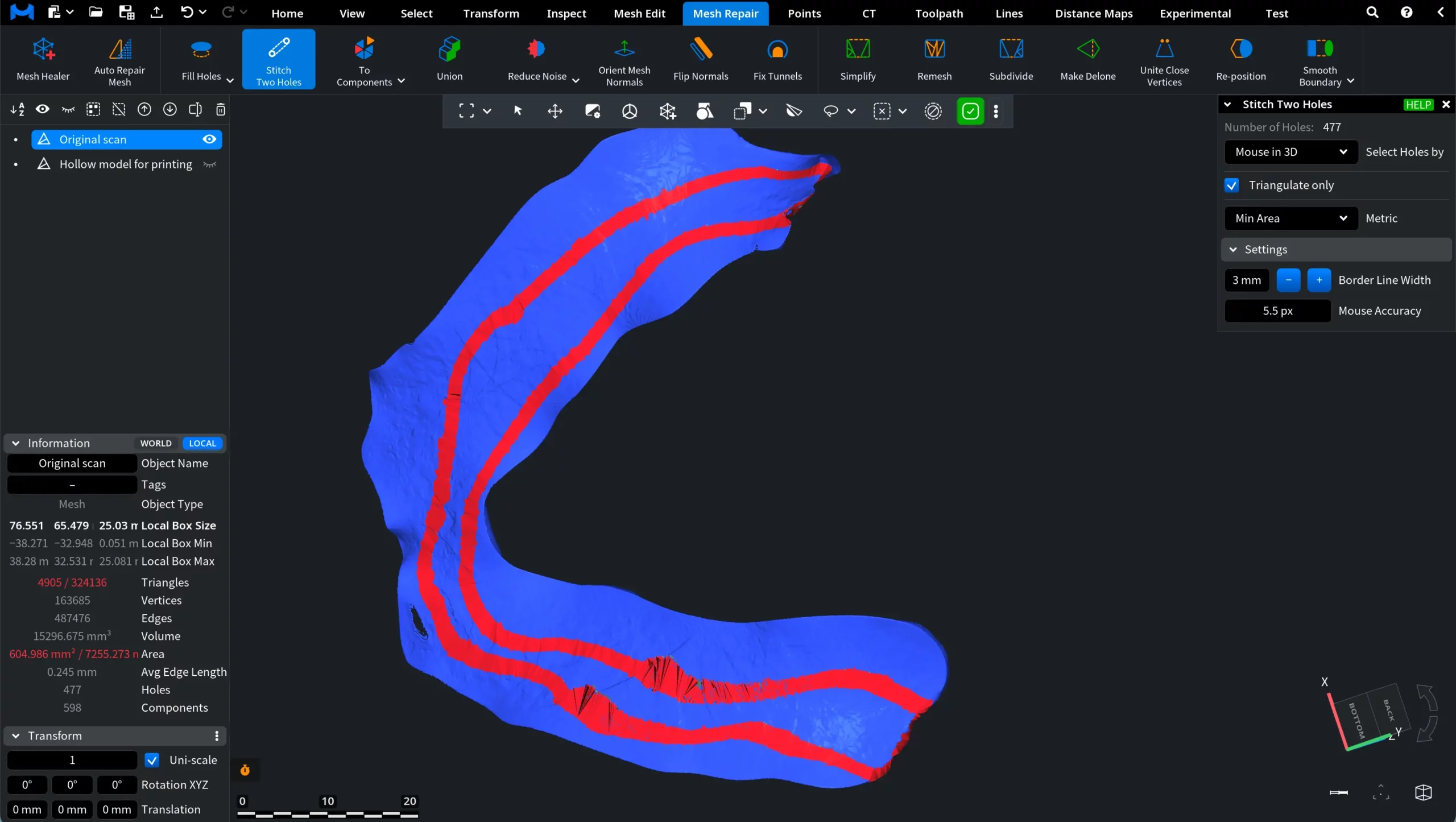
This approach produces a more accurate result compared to Fill Holes, as it restores the connection between corresponding boundaries rather than closing the interior volume.
Stitch Two Holes: Controls and Settings
You can fine-tune the stitching operation, for both the resulting geometry and the interaction workflow.
Select Holes by
Select Holes by determines how hole boundaries are selected for stitching. You can either select holes directly in the 3D view using the mouse or specify them by their hole ID in the dialog.
Selecting holes with the mouse allows you to interactively click the desired boundary in the viewport, while selecting by hole ID lets you reference the holes detected in the mesh.
Mouse in 3D
With Mouse in 3D selected, move the cursor over the boundary of a hole in the viewport. When the cursor reaches the boundary, it is highlighted in red, indicating that the hole can be selected.
Click the boundary to select the first hole. The selected boundary becomes green. Then move the cursor over the boundary of the second hole. It will also be highlighted in red.
Click the second boundary to start the stitching operation, as you have already seen above.
Hole ID
When Hole ID is selected in Select Holes by, the holes to be stitched are specified using their numeric identifiers instead of selecting them directly in the 3D view. That is, MeshInspector assigns each hole a unique Hole ID: these identifiers allow you to precisely specify which holes should be stitched together.
Enter the corresponding numbers in First Hole ID and Second Hole ID. The selected hole boundaries are highlighted in the viewport, allowing you to verify that the correct holes have been chosen. To perform the operation, click Stitch Holes.
Triangulate only
When Triangulate only is enabled, the patch created between the selected holes is generated using only triangles that directly connect the hole boundaries. If this option is disabled, MeshInspector may insert additional vertices inside the patch. These extra vertices allow the algorithm to produce a more regular triangulation and improve the overall mesh quality of the stitched area.
Metric
Metric defines the optimization strategy used to generate the triangulated patch between the selected holes. Different metrics prioritize different geometric properties of the resulting triangulation:
- Min Area minimizes the total area of the surface patch created between the holes. It is a good choice when the hole has an irregular or degenerate shape, or when it is surrounded by degenerate triangles.
- Universal minimizes the maximal dihedral angle between the faces in the triangulation and along its boundary. This helps avoid creating highly degenerate triangles. For planar holes, this metric behaves the same as the Circumscribed metric.
- Complex minimizes a combined metric that includes both triangle quality and edge consistency in the triangulation. The optimization minimizes the total triangle metric across all triangles together with the edge metric across all edges inside and on the boundary of the triangulation. The triangle metric is proportional to the weighted triangle area and triangle aspect ratio, while the edge metric increases with the angle between adjacent triangles. This approach typically produces balanced triangulations for complex hole shapes.
- Circumscribed minimizes the sum of the circumcircle radii for all triangles in the triangulation. It is relatively fast to compute and typically produces good triangulations.
Settings
Border Line Width controls the visual thickness of the highlighted hole boundary in the viewport. Increasing this value makes the hole contour easier to see when selecting boundaries, especially on complex meshes or when working at a distance. Decreasing the value makes the highlight thinner.
Mouse Accuracy defines how close the mouse cursor must be to a hole boundary for it to be detected and highlighted in the viewport. If the cursor is within the specified distance (in pixels), the boundary becomes highlighted and can be selected. Increasing this value makes it easier to select hole boundaries from a greater distance, while decreasing it requires more precise cursor placement. This option is available only when Mouse in 3D is selected in Select Holes by.
Options when Triangulate only is Disabled
If Triangulate only is disabled, MeshInspector generates a higher-quality patch by inserting additional vertices inside the stitched region. This allows the algorithm to better adapt the new surface to the surrounding mesh and improve geometric continuity. In this mode, several additional parameters become available.
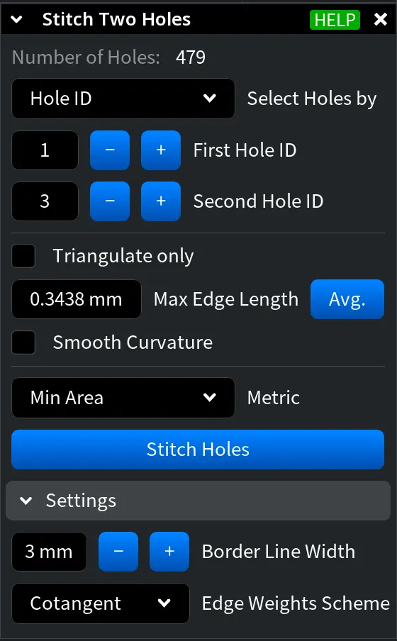
Max Edge Length defines the maximum allowed length of edges created inside the generated patch. This parameter helps control the density of the triangulation inside the stitched region. Smaller values produce a denser mesh with shorter edges, while larger values generate fewer triangles and a coarser patch.
When Avg. is enabled, the value is automatically computed based on the average edge length of the mesh.
Smooth Curvature smooths the generated stitch both inside the patch and along its boundary with the existing surface. When enabled, the algorithm attempts to better match the curvature of the surrounding geometry, producing a smoother transition between the stitched region and the original mesh.
Edge Weights Scheme determines how edge weights are assigned during the surface smoothing process. Two schemes are available:
- Unit. All edges have the same weight.
- Cotangent. Edge weights depend on the local geometry and are computed using cotangent values. This scheme adapts to the shape of the mesh and often produces smoother and more natural results.