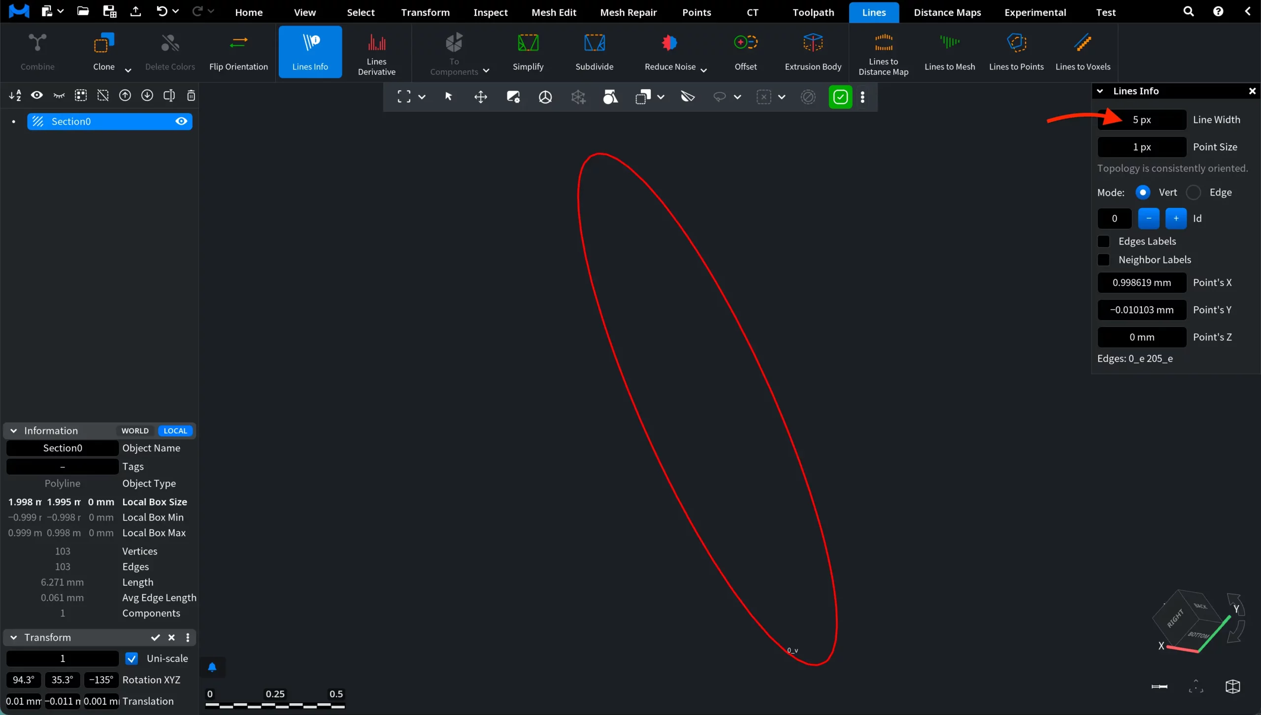
Working with polylines often necessitates inspecting their internal structure and connectivity. For this purpose, MeshInspector provides the Lines Info tool, which displays detailed information about lines and their primitives. To access this tool, open the Lines tab in the top toolbar and click Lines Info, as shown in the screenshot below. Once activated, the tool opens the Lines Info panel, where you can examine various properties of the selected line elements.

Once you click Lines Info, a dedicated panel appears on the right side of the viewport. This panel provides detailed information about the structure of the selected line object and allows you to inspect its elements. You can adjust the inspection settings to match your needs.

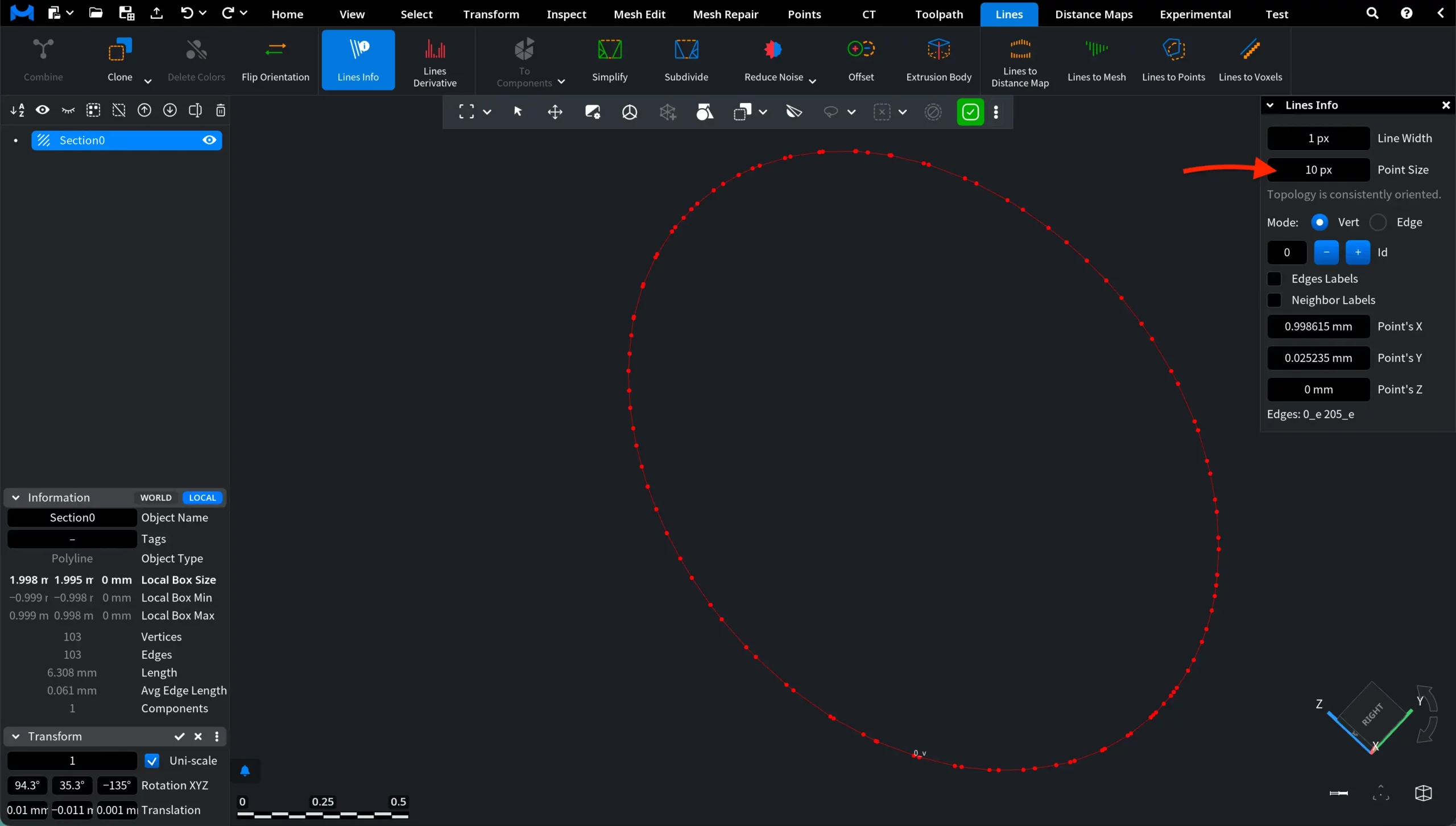
Lines Info: Settings
Line Width
The Line Width parameter controls how thick the lines are displayed in the viewport. Increasing this value makes the polyline visually thicker, which can improve visibility when inspecting line structures or working with complex scenes. Adjusting the line width can be particularly useful when working with very thin lines that may be difficult to see at certain zoom levels. As with other numeric fields here, you can either enter a value manually or adjust it by dragging.

Neighbor Labels displays the identifiers of the neighboring vertices connected to the selected vertex (for example, 22_v). These labels help you quickly identify the adjacent points that form the polyline.
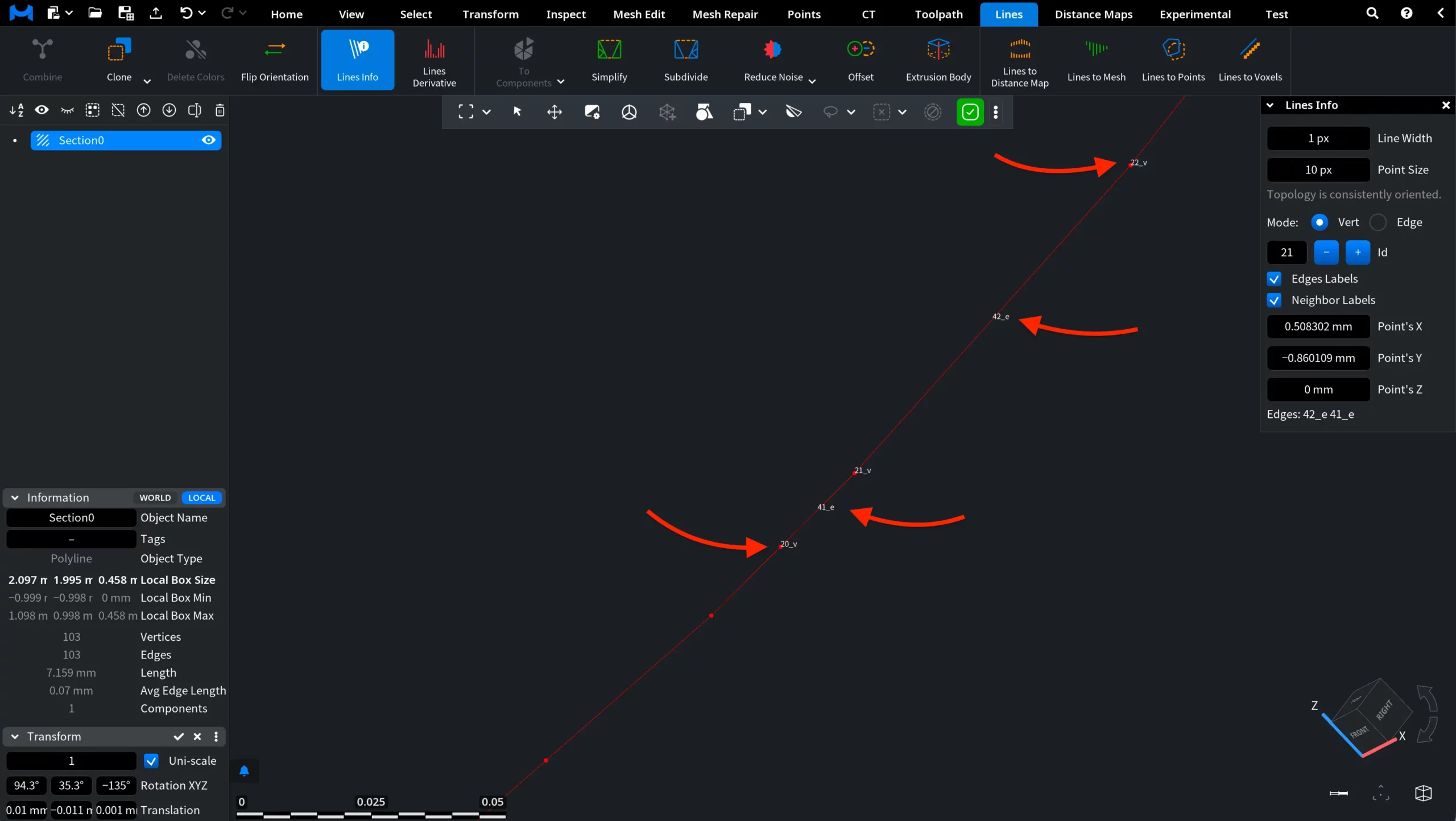
The panel also displays the coordinates of the selected vertex:
- Point's X
- Point's Y
- Point's Z
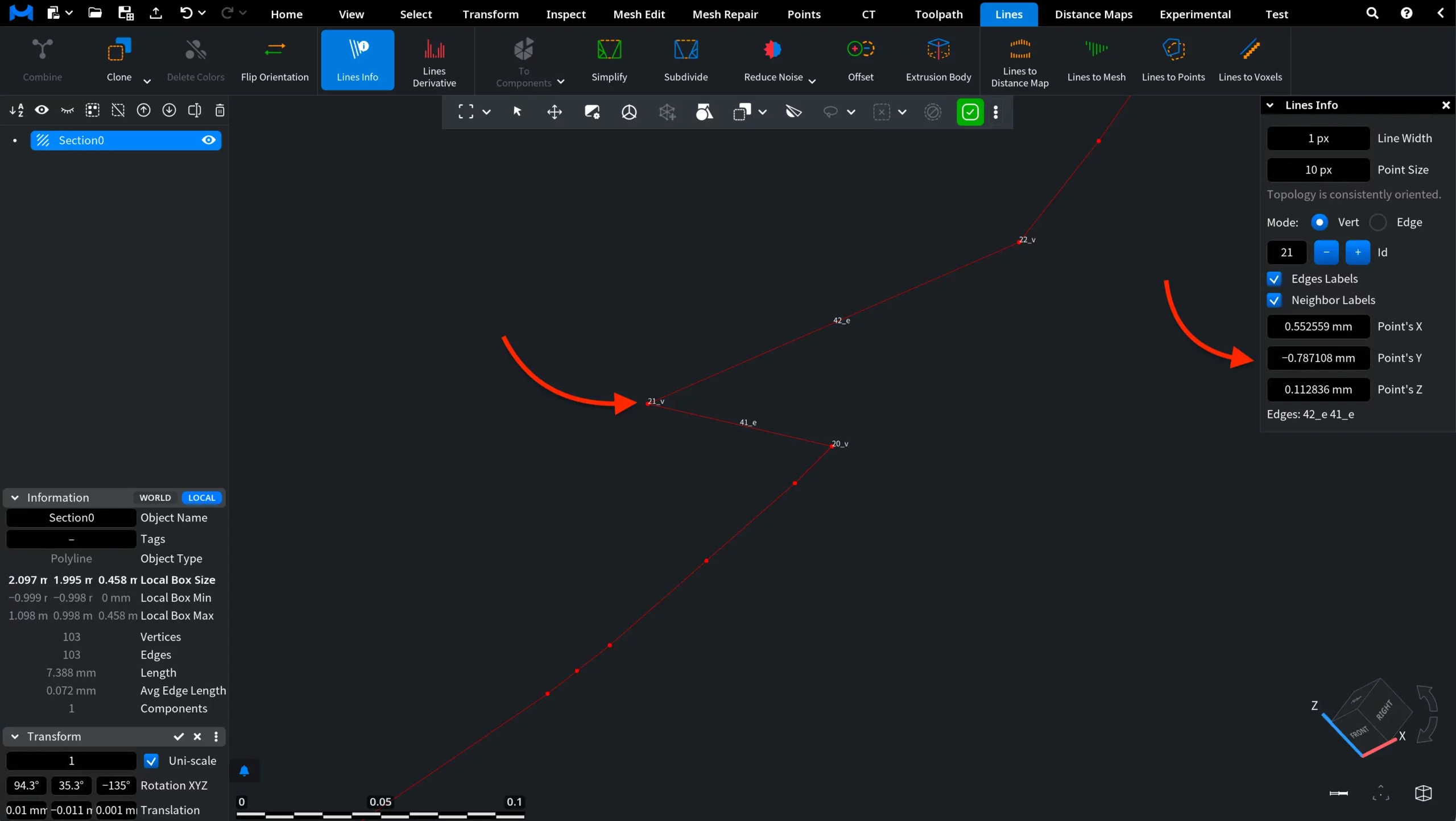
These values represent the exact spatial position of the vertex. Changing them moves the selected vertex in the scene, which updates the shape of the polyline accordingly, as shown below.
At the bottom of the panel, the Edges field lists the identifiers of the edges connected to the selected vertex (in this example, 42_e 41_e).
Edge
In Edge mode, the Lines Info tool allows you to inspect individual edges of the polyline.
Id. Each edge has its own Id, which can be navigated using the – / + buttons next to the Id field. As you switch between edges, the selected edge is highlighted in the viewport, allowing you to clearly see which segment of the polyline is currently being inspected.
Vert labels displays the identifiers of the two vertices that define the selected edge.
Neighbor labels displays the identifiers of the vertices adjacent to the selected edge.
Next / Prev navigates to the adjacent edge connected to the current edge according to the polyline topology. This allows you to move between connected edges and inspect their relationships.
Sym selects the symmetric edge, which represents the same segment but with the opposite internal direction.
Below these controls, additional topology information is displayed:
- VertId shows the identifiers of the two vertices that define the edge (in their internal order).
- Next / Prev displays the identifier of the adjacent edge connected to the current edge in the polyline topology.
- Sym shows the identifier of the symmetric edge representing the same segment with the opposite orientation.