Line objects by themselves have no thickness. They are just paths. This becomes a limitation when you need actual geometry for further operations. The Extrusion Body tool addresses this by turning abstract line structures into a real mesh. The tool is located in the Lines tab on the top toolbar. It creates a mesh by extruding one object’s lines along another one, allowing you to generate volumetric geometry from line-based structures.

Once a line object is loaded and visible in both the Scene tree and the viewport, the Extrusion Body button becomes active. Click it to open a dedicated panel on the right with settings and controls.
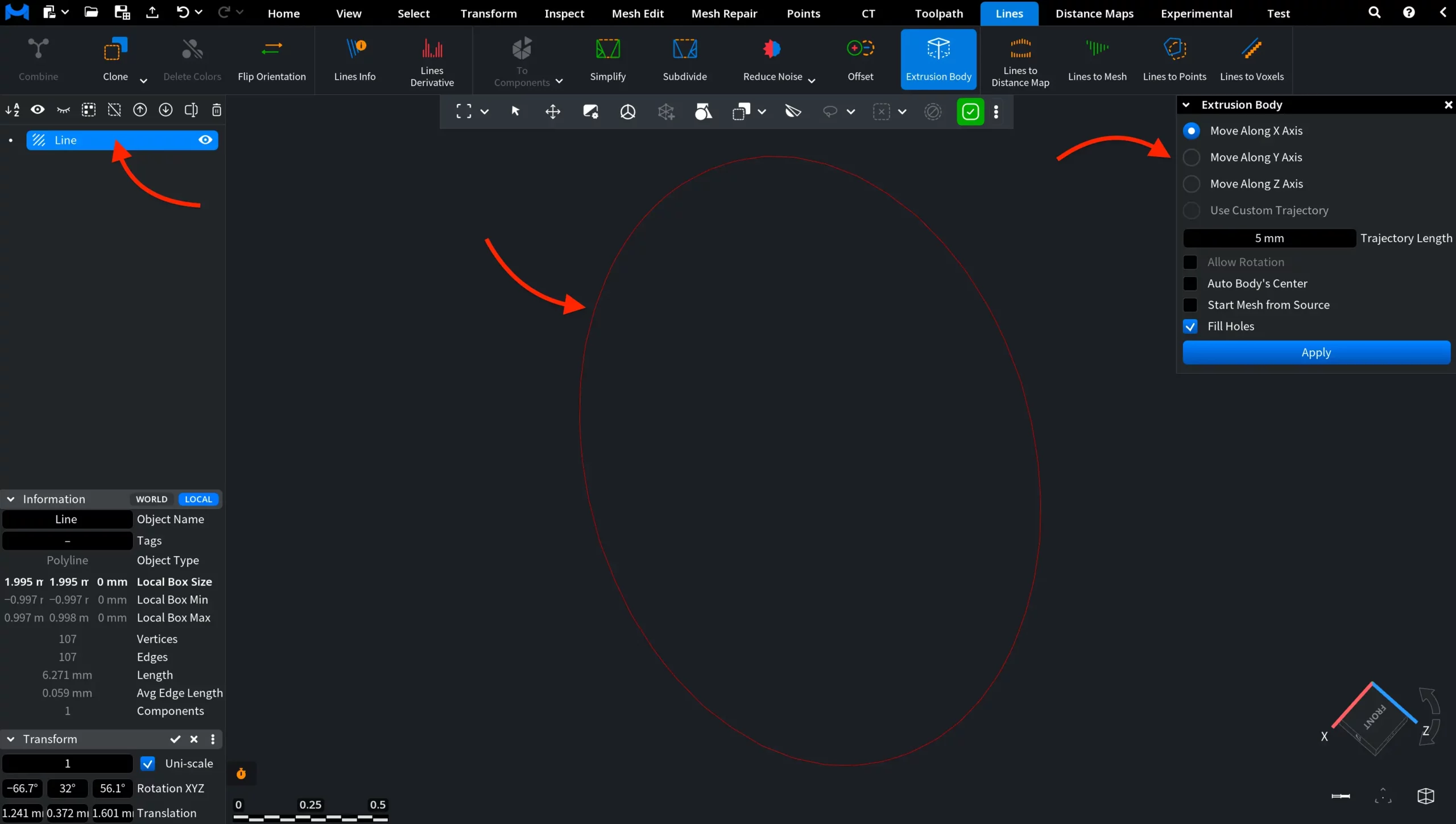
Extrusion Body: Settings and Controls
Here is how MeshInspector allows you to fine-tune the extrusion process and its results.
X, Y, Z Axes
- Move Along X Axis extrudes the line along the X direction.
- Move Along Y Axis extrudes the line along the Y direction.
- Move Along Z Axis extrudes the line along the Z direction.
Only one axis can be active at a time. The selected axis determines where the generated mesh extends relative to the original line object.
Trajectory Length
Trajectory Length controls how far the extrusion extends along the selected direction.
- Smaller values generate shorter, more compact geometry.
- Larger values generate longer, more elongated mesh.
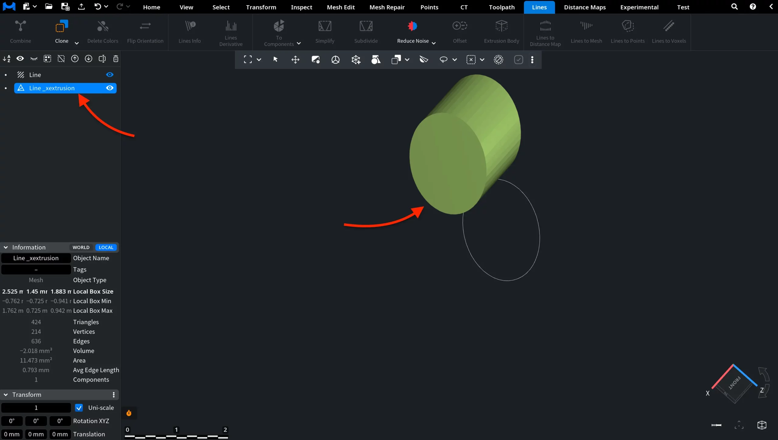
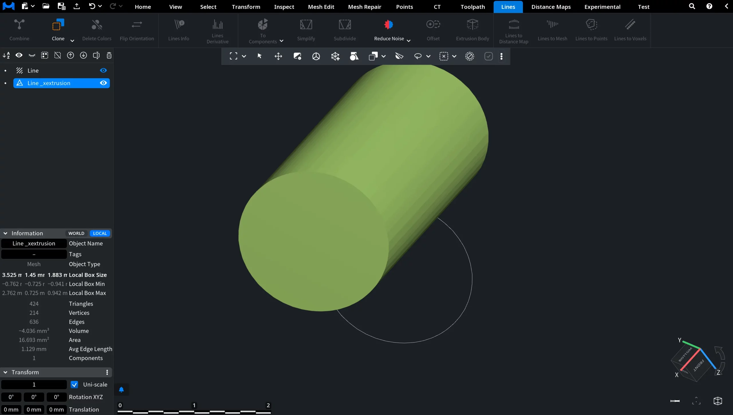
In the screenshot below you can see the result of an extrusion operation performed along the X axis with a trajectory length of 1 mm.
Use Custom Trajectory
Use Custom Trajectory becomes available when multiple line objects are present in the Scene tree. When enabled, extrusion is performed along another line object. In this case, use the Trajectory dropdown to select which line object will define the extrusion path.
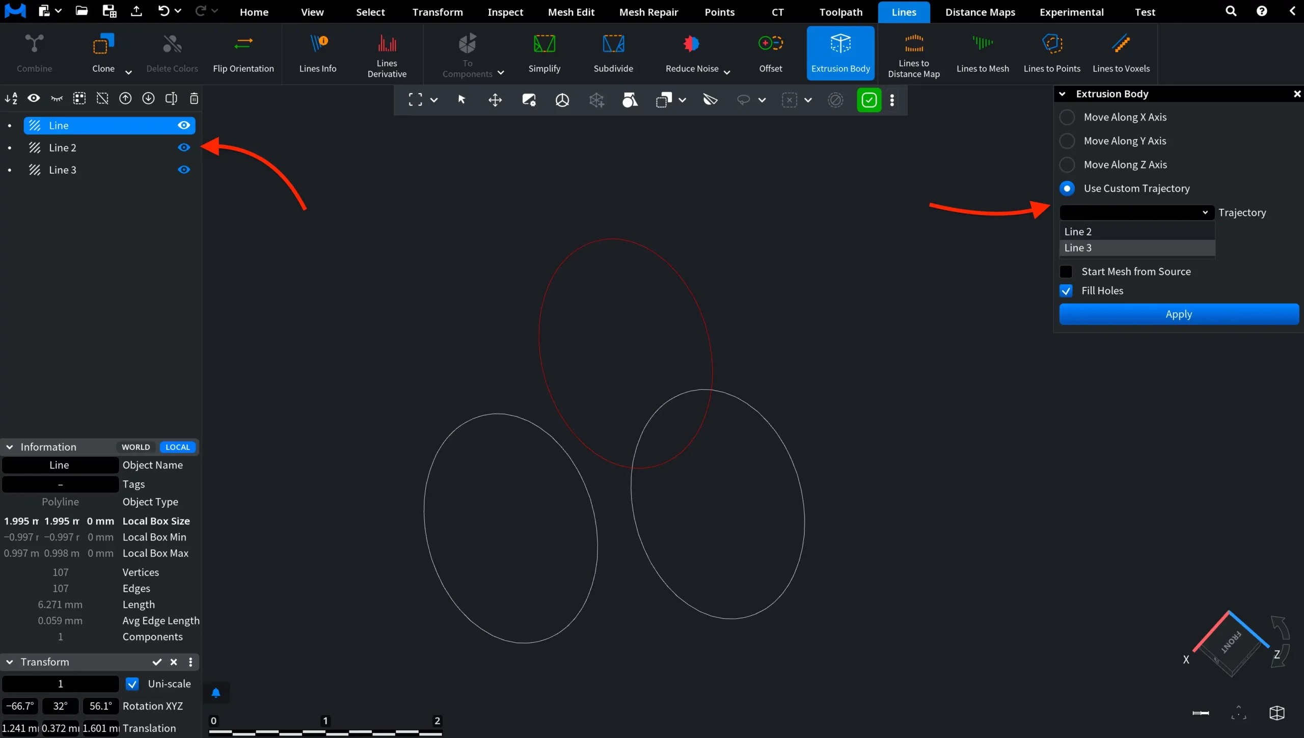
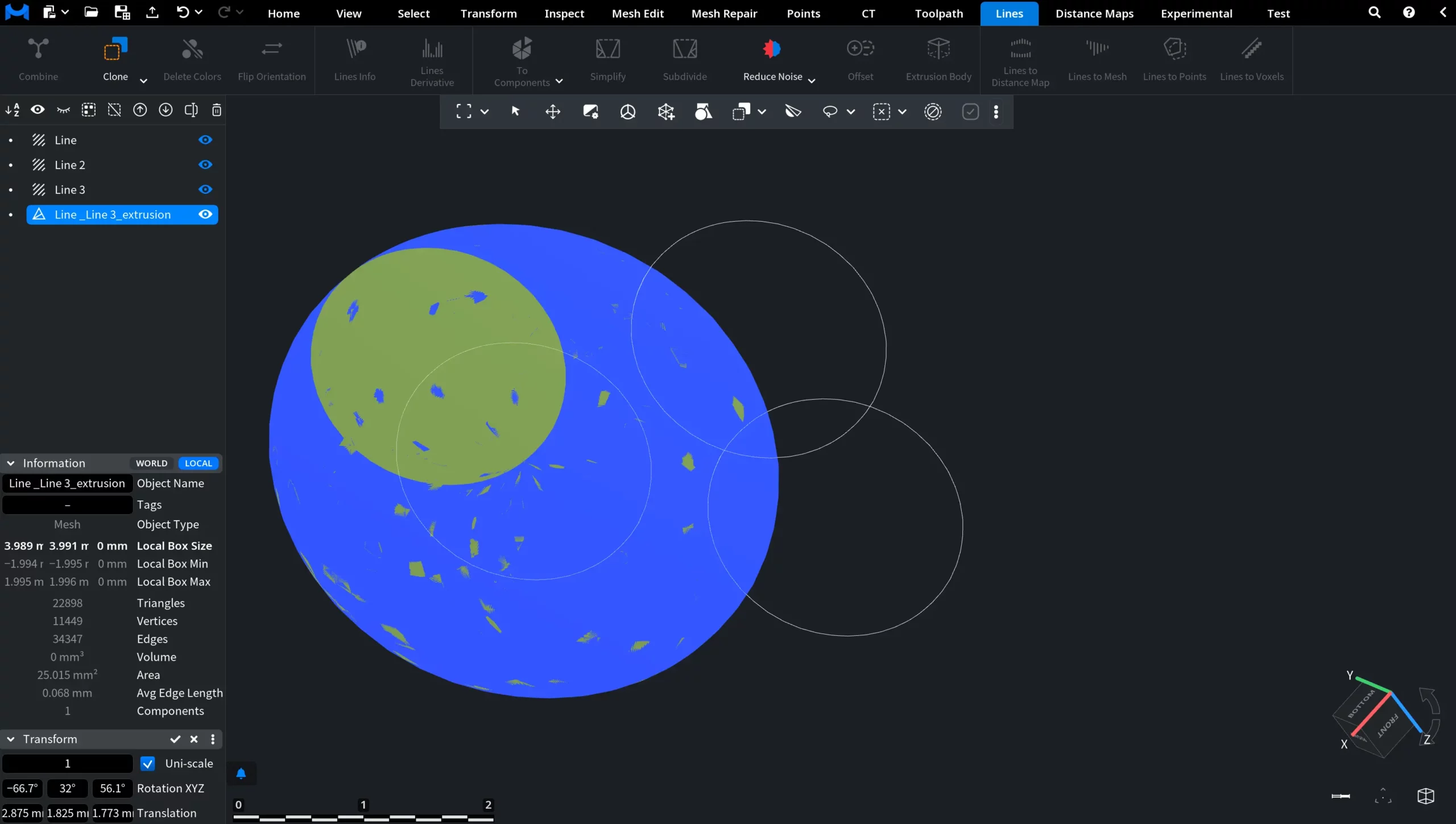
The selected trajectory defines the result of the Extrusion operation. In the example below, the Line object is selected as the source, and extrusion is performed using Line 3 as the custom trajectory.
Allow Rotation
Allow Rotation (available only with more than one line), when enabled, rotates the body along the trajectory vertices. When off, only translation along the trajectory is applied. The result can be seen in the screenshot below. We took Line as the source object, Line 2 as the custom trajectory, and enabled Allow Rotation.
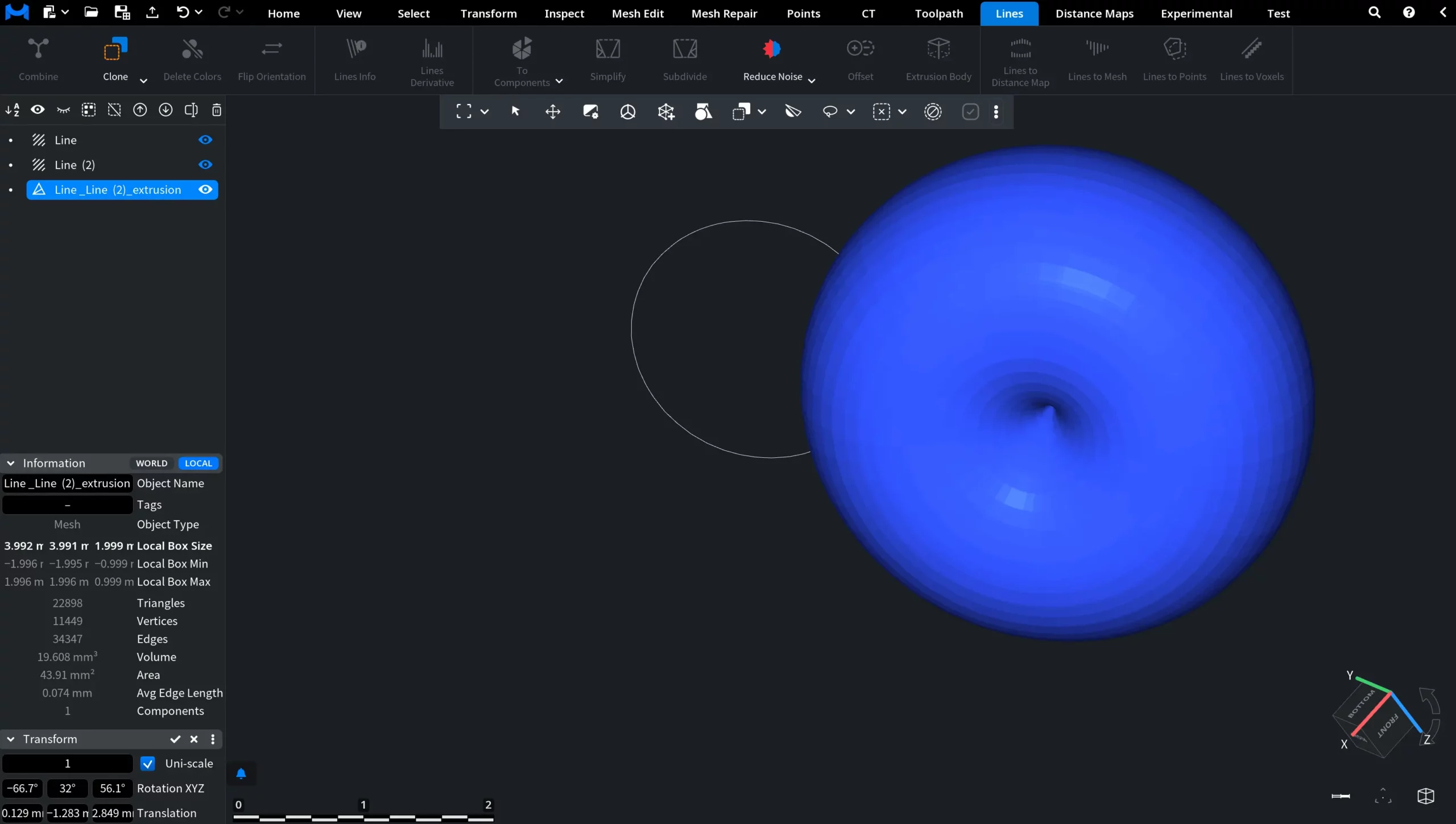
As a result, the geometry follows the trajectory in position and orientation, producing a smooth, continuous shape that wraps around the path.
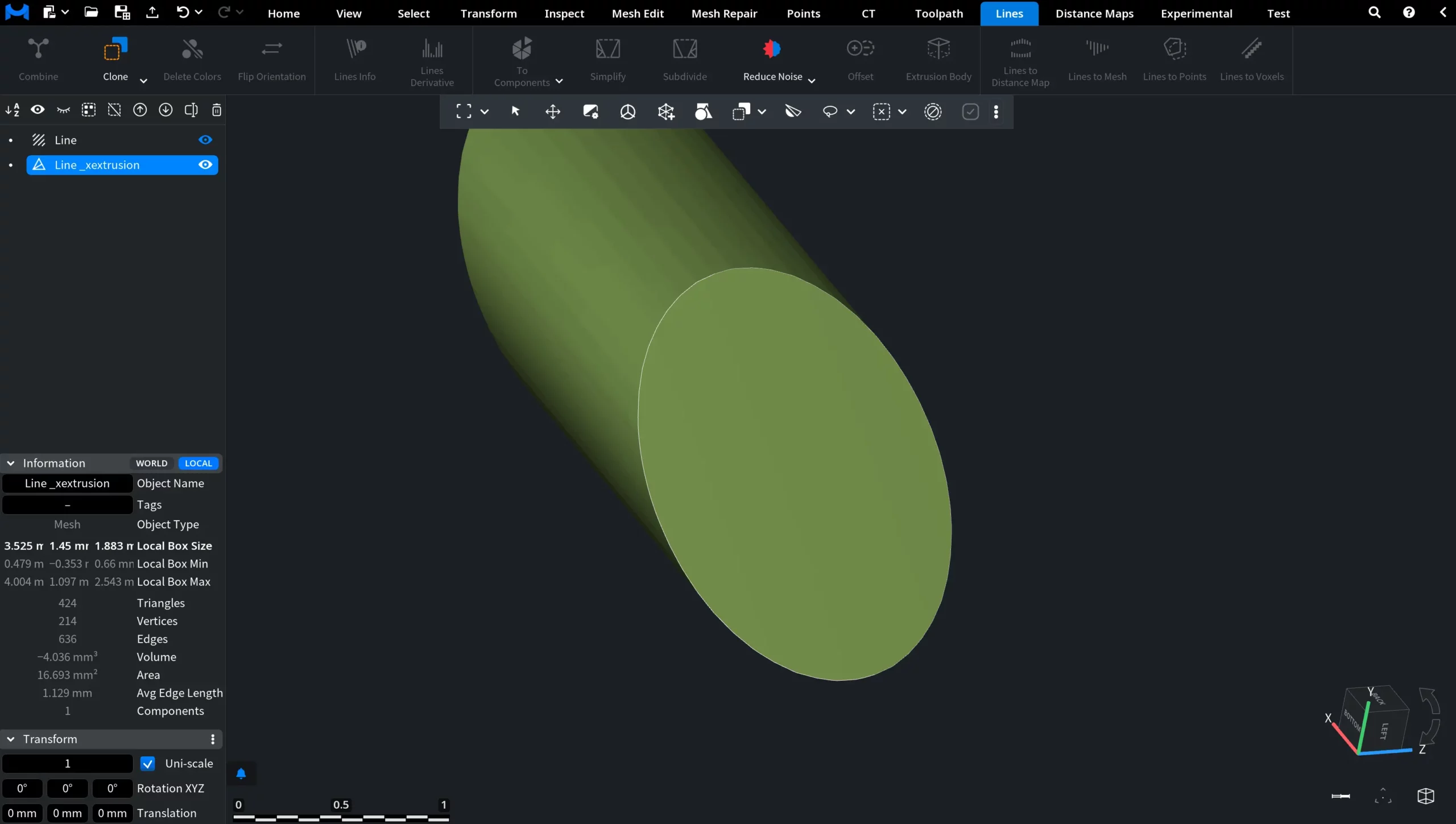
Auto Body’s Center
Auto Body’s Center, when enabled, aligns the generated mesh relative to its center during extrusion. When off, the extrusion is performed based on the original position of the source line. The result can be seen in the screenshot below. With Auto Body’s Center enabled, the resulting mesh is positioned symmetrically.
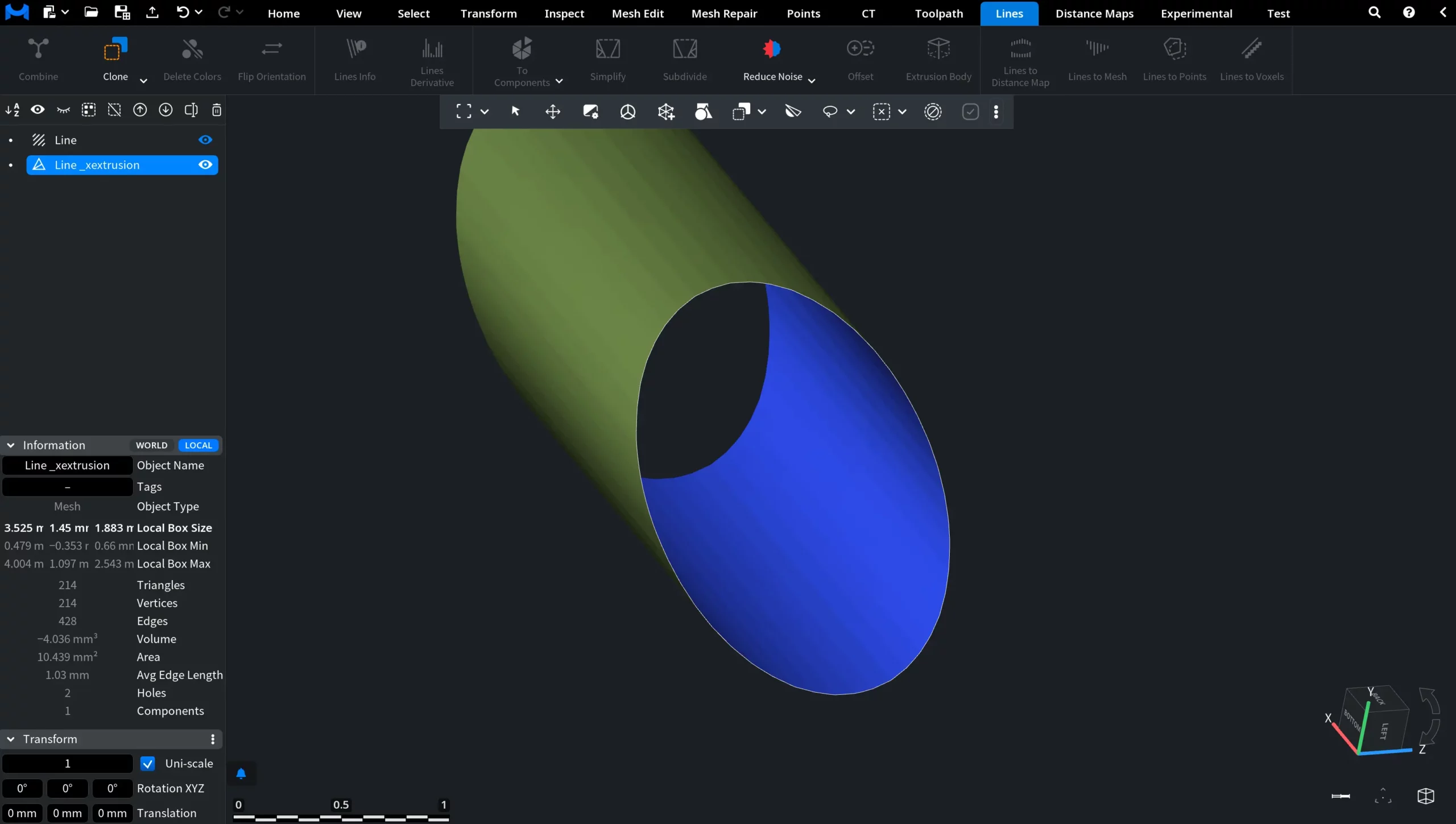
Start Mesh from Source
Start Mesh from Source, when enabled, starts the extrusion directly from the source line object. When off, the generated mesh is offset from the original line. The result can be seen in the screenshot below. With Start Mesh from Source enabled, the mesh begins at the position of the source line.