How the Lines to Distance Map Tool Works in MeshInspector
Overview of the Lines to Distance Map Tool
Updated over 2 months ago
Polylines define shapes and paths. However, they do not provide distance information for the surrounding space. This may become a limitation when you need to evaluate how far any point is from a line or analyze areas influenced by it.
MeshInspector provides a tool for this. The Lines to Distance Map tool converts line objects into a distance map, where each pixel stores the distance to the nearest point on the line. The tool is located in the Lines tab on the top toolbar.
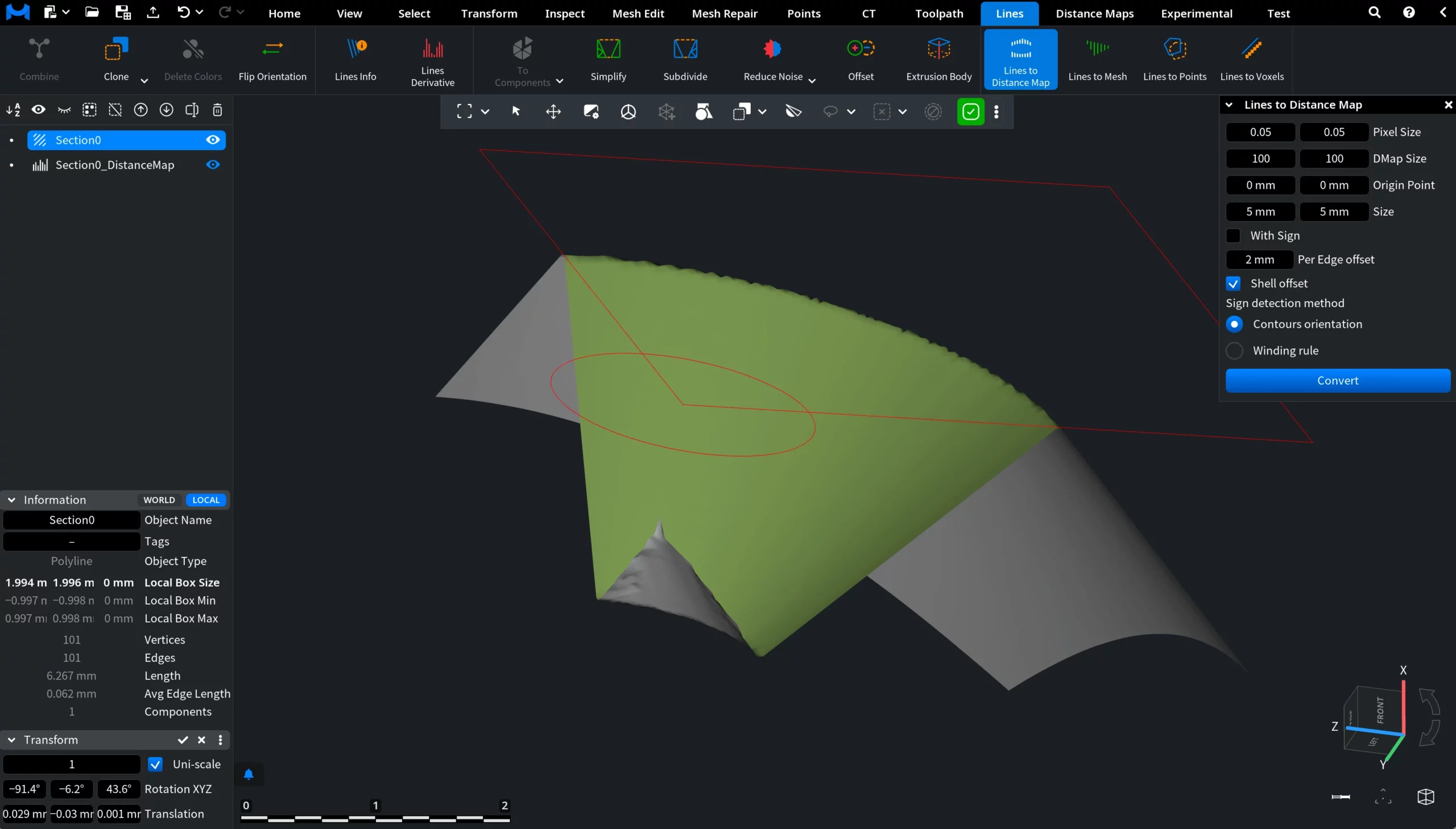
Once you click the Lines to Distance Map tool, a dedicated panel appears on the right with settings and controls.
In the viewport, an additional red overlay becomes visible, in addition to the source polyline. This overlay represents the area where the distance map will be generated. It appears only in the viewport and is not added as a separate object in the Scene tree.
Lines to Distance Map: Settings and Controls
MeshInspector provides a set of settings to configure before committing the operation.
Pixel Size
Pixel Size defines the physical size of each pixel in the distance map. Smaller values increase precision, while larger values produce a coarser representation. In the example below, the Pixel Size was slightly increased to demonstrate its effect. As the value grows, the resulting distance map becomes less precise, and fine details of the original polyline are represented more coarsely.
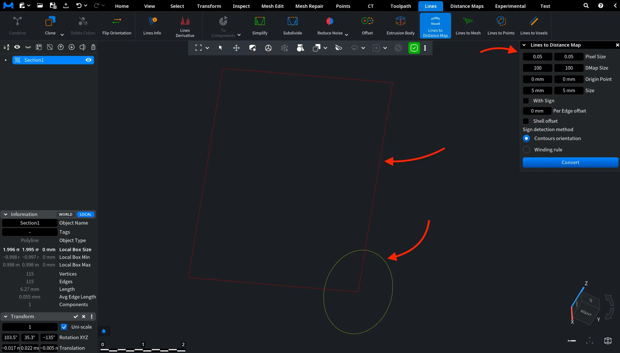
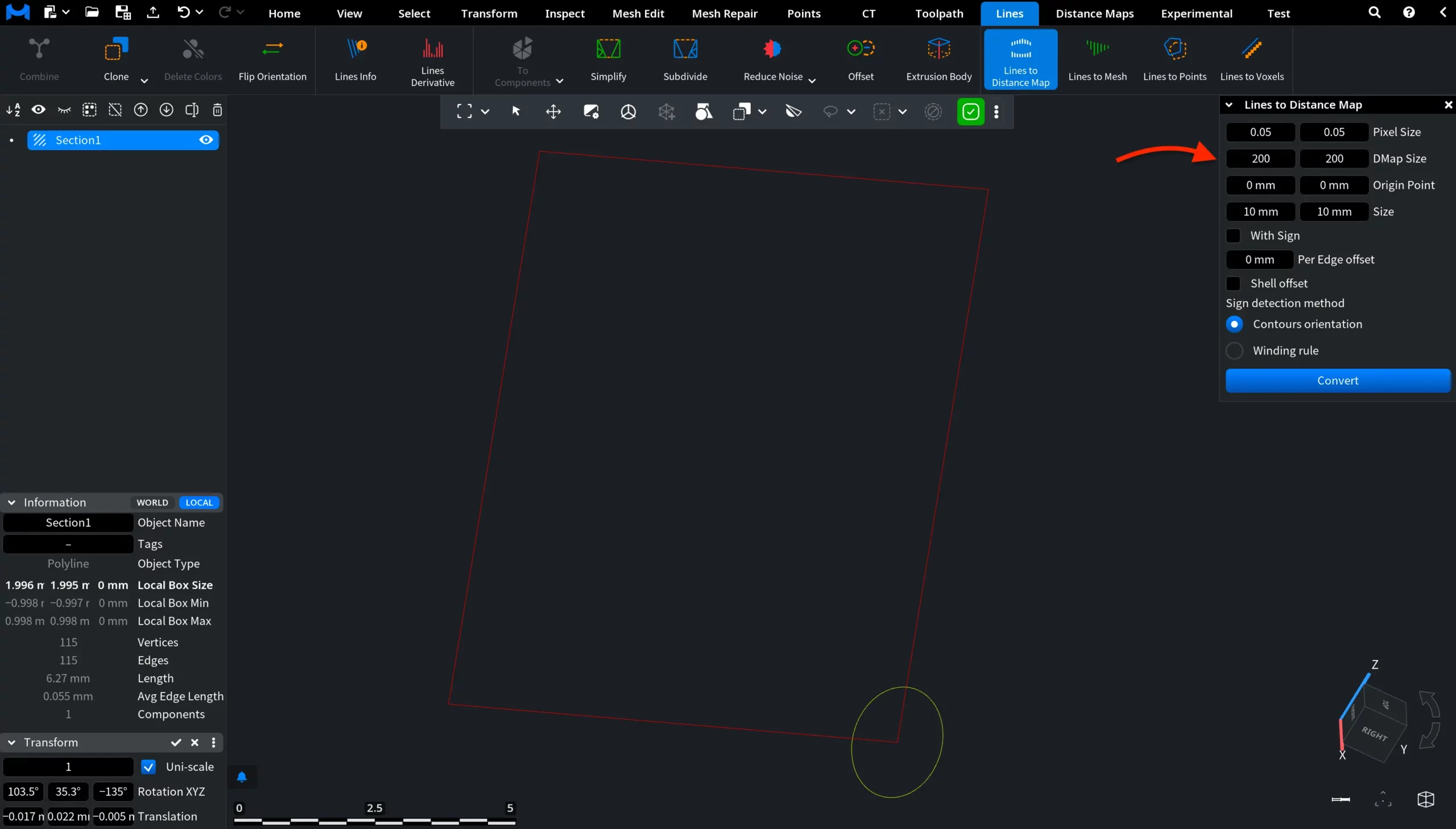
DMap Size
DMap Size defines the number of pixels used to represent the distance map. Increasing this value raises the resolution by adding more pixels within the same area:
Smaller values mean lower resolution and less detail
Larger values mean higher resolution and more detailed representation
By default, the value is set to 100 × 100. In the example below, the DMap Size was increased to 200 × 200, resulting in a denser and more refined distance map within the same area.
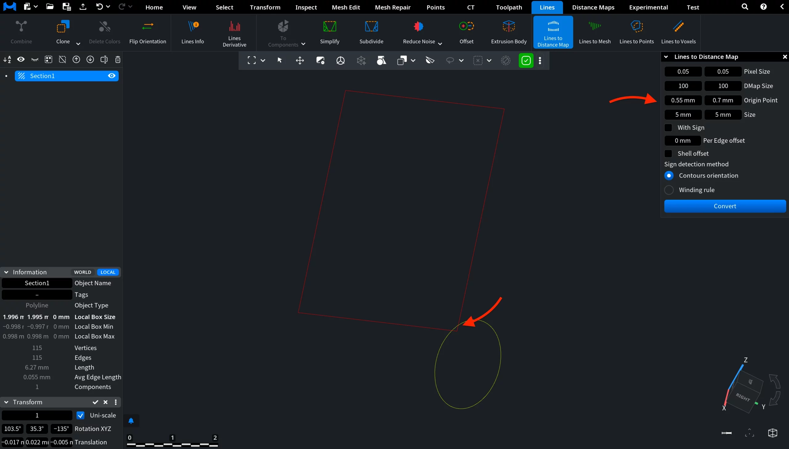
Origin Point
Origin Point defines the position of the distance map in the scene. It sets the reference point from which the distance map area is generated. Changing this value shifts the red preview area in the viewport without altering its size or resolution. In the example below, the Origin Point was adjusted to move the distance map.
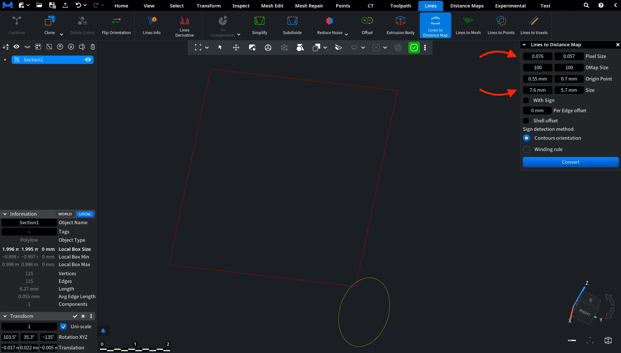
Size
Size defines the physical dimensions of the distance map area in the scene. It controls how large the generated map is in units. Changing this value expands or shrinks the red preview area in the viewport. Size is directly related to Pixel Size, while DMap Size remains unchanged. When you adjust Size, Pixel Size is recalculated to fit the same number of pixels (i.e., DMap Size) into a larger or smaller area.
With Sign
With Sign, when enabled, converts the distance map from an unsigned field into a signed one. In this mode, the polyline defines a zero-distance reference that separates the field into two sides. Distances on one side of the line are stored as positive values, while distances on the other side are stored as negative values. As a result, the distance map no longer behaves symmetrically. Instead, it reflects spatial relationships relative to the line, which is useful for directional analysis, inside/outside classification, and advanced geometric operations.
The assignment of positive and negative regions depends on the orientation of the polyline and the selected sign detection method.
When With Sign is disabled, the distance map stores only absolute distances to the nearest line. All values are non-negative, and no distinction is made between different sides of the polyline.
You can look at the screenshots below to understand the difference.
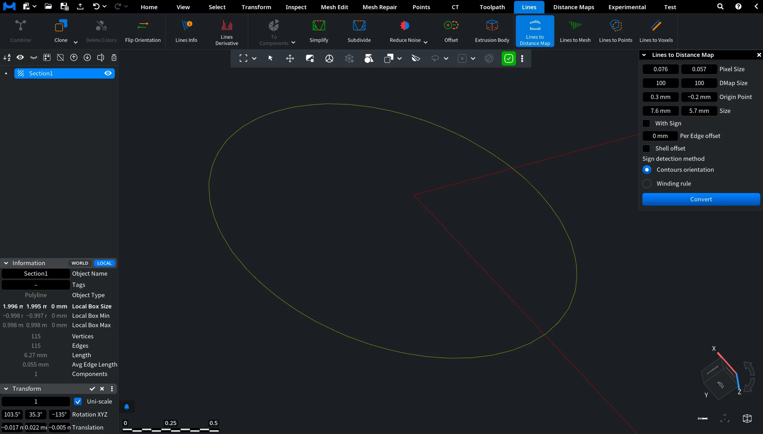
Before conversion
The original polyline before generating the distance map.
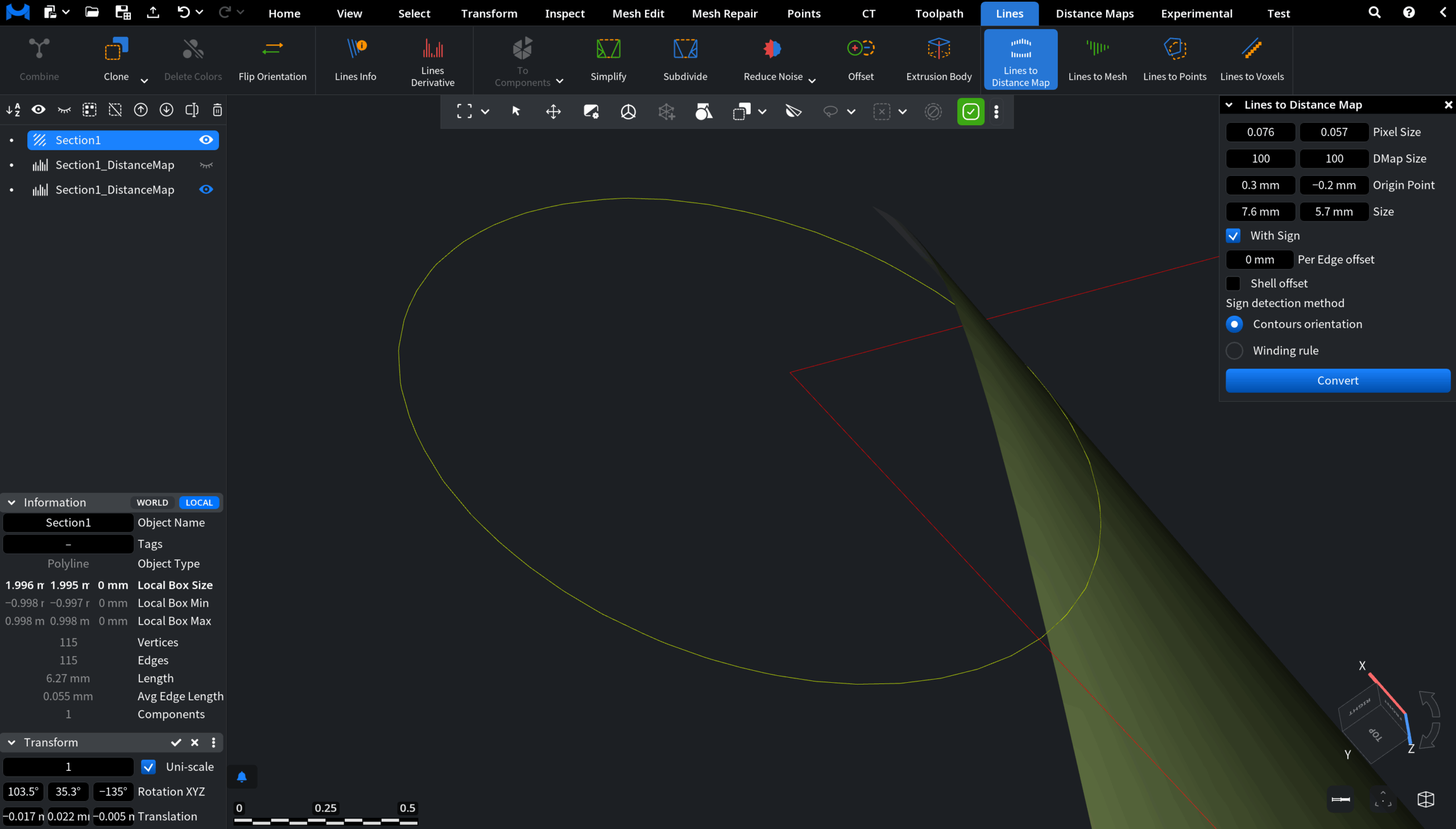
After Conversion: With Sign On
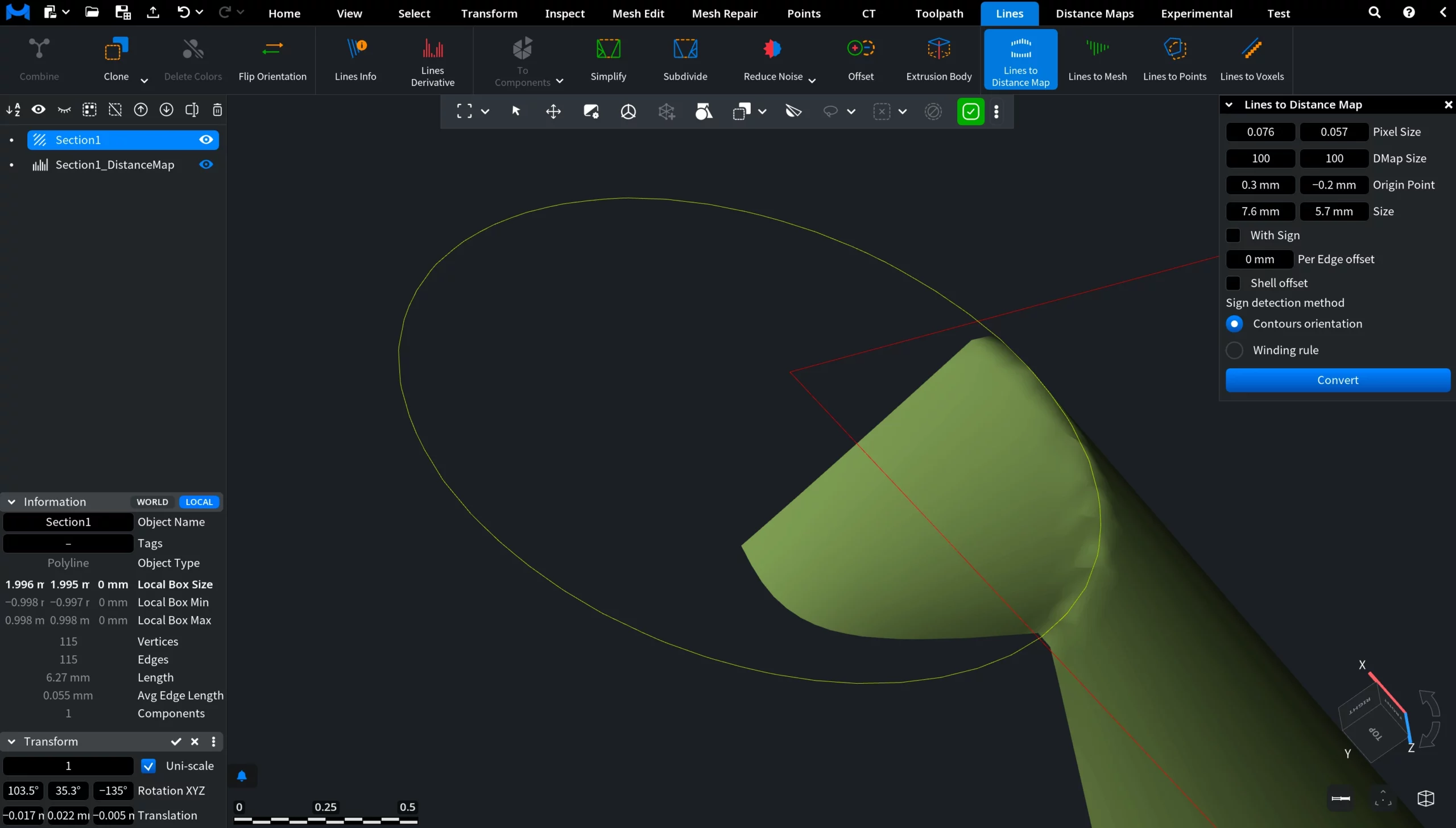
After Conversion: With Sign Off
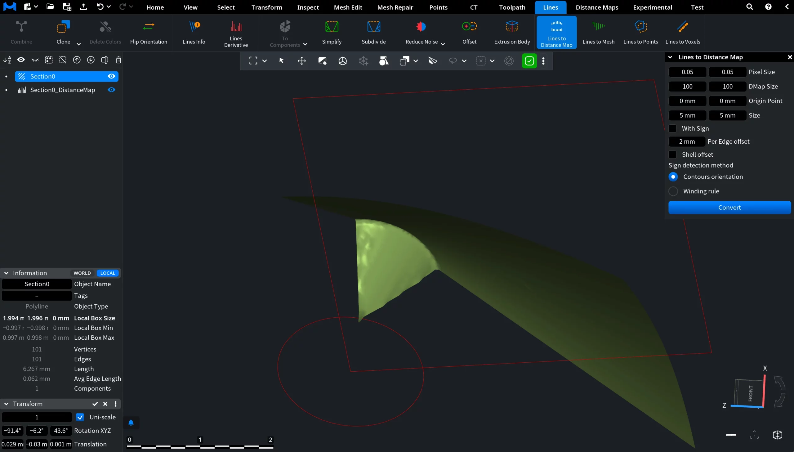
Per Edge Offset
Per Edge Offset defines an additional offset distance applied relative to the source polyline during distance map generation. Instead of using the original line as the zero-distance reference, the tool computes distances from an offset contour positioned at the specified value from each edge. This allows the generated distance field to begin not exactly from the source polyline, but from a shifted boundary around it.
Shell offset
Shell Offset controls how the Per Edge Offset is applied. When Shell Offset is disabled, the offset contour is generated only on one side of the polyline edges. When Shell Offset is enabled, the same offset is applied symmetrically on both sides of the polyline, creating a shell-like expanded region around the original line.
Sign detection method
Guide to the Lines to Distance Map Tool in MeshInspector