Under the Toolpath tab, you can find the Toolpath button. It allows you to build a Z-constant toolpath for the selected mesh. The tool calculates tool movements based on the mesh geometry and creates a toolpath object that can be inspected in the viewport.

Before using the Toolpath tool, make sure your object is perfectly aligned with the Z-axis, as shown in the screenshot below. If it is not, align it using MeshInspector's Align to Plane tool.
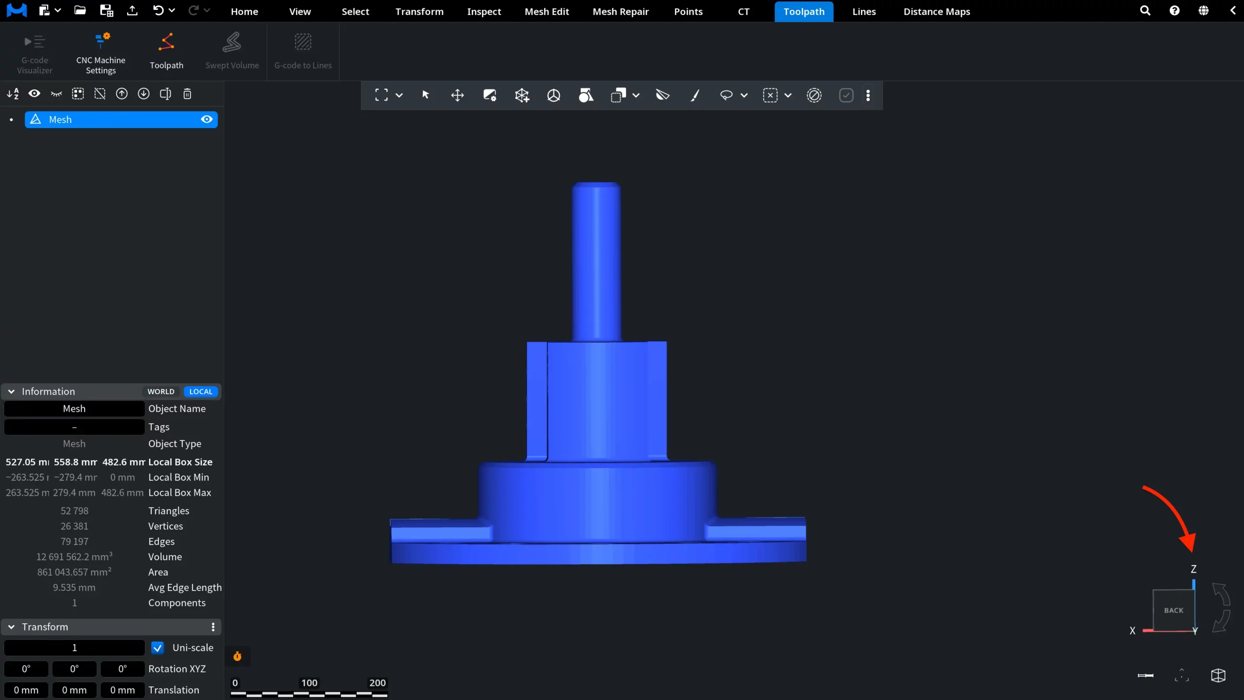
To use the tool, select a single aligned mesh object in the scene and click Toolpath. MeshInspector opens a dedicated panel with toolpath generation settings. The panel contains common toolpath parameters, interpolation settings, feedrate settings, and the Create Tool Path button used to generate the toolpath.
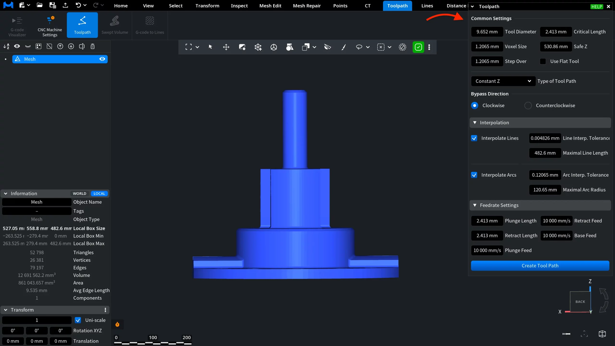
Common Settings
The Common Settings section contains the main parameters used to generate the toolpath.
- Tool Diameter defines the milling tool size. This value is used as the radius of the milling tool.
- Critical Length defines how MeshInspector handles transitions between sections. If the distance to the next section is smaller than this value, the transition is performed along the surface. Otherwise, the transition is performed through the safe plane.
- Voxel Size defines the voxel size needed to offset the mesh.
- Safe Z defines the Z-coordinate of the plane where the tool can move in any direction without touching the object.
- Step Over defines the distance between sections built along the Z-axis.
- Use Flat Tool generates the toolpath for a flat milling tool.
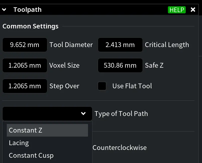
Finally, Type of Tool Path allows you to select the toolpath generation mode. The available options include:
- Constant Z
- Lacing
- Constant Cusp
Bypass Direction
The Bypass Direction section allows you to select either Clockwise or Counterclockwise movement around the geometry.
Interpolation
The Interpolation section controls how line and arc segments are optimized when the toolpath is generated.
You can enable or disable:
- Interpolate Lines
- Interpolate Arcs
When these options are disabled, the related settings are hidden.
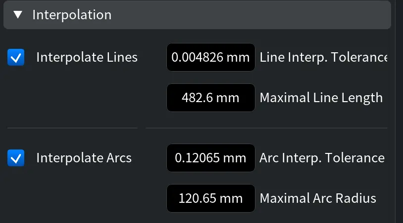
If Interpolate Lines is enabled, you can configure:
- Line Interp. Tolerance, which defines the maximum deviation of a line from the given path.
- Maximal Line Length, which defines the maximum line segment length to be optimized. Segments longer than this value will not be optimized.
If Interpolate Arcs is enabled, you can configure:
- Arc Interp. Tolerance, which defines the maximum deviation of an arc from the given path.
- Maximal Arc Radius, which defines the maximum arc radius to be optimized. Segments will not be optimized if the arc radius is greater than this value.
Feedrate Settings
The Feedrate Settings section defines the movement speeds used when the toolpath is generated.
- Plunge Length defines the distance from the mesh at which the milling tool slows down while moving down.
- Retract Length defines the distance from the mesh at which the milling tool slows down while moving up.
- Retract Feed defines the speed of slow upward movement.
- Base Feed defines the speed of regular milling.
- Plunge Feed defines the speed of slow downward movement.
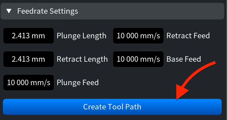
After configuring the required parameters, click Create Tool Path to generate the toolpath.
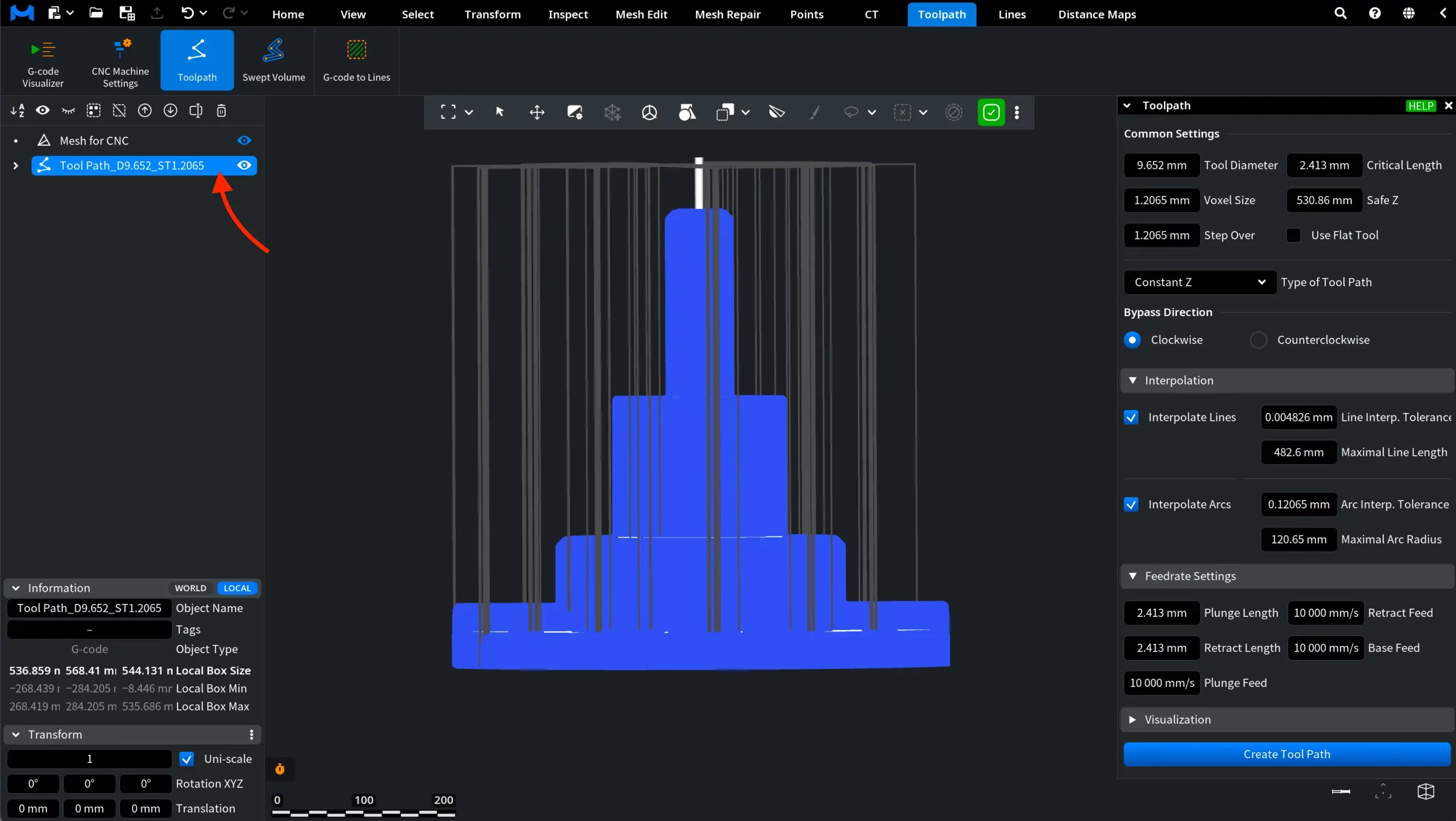
A new toolpath object appears in the Scene Tree and can be inspected in the Viewport. In the examples below, the default settings were used with the Use Flat Tool option disabled. When Use Flat Tool is disabled, MeshInspector generates a toolpath without applying the flat milling tool mode. The resulting path follows the selected mesh according to the current toolpath settings.
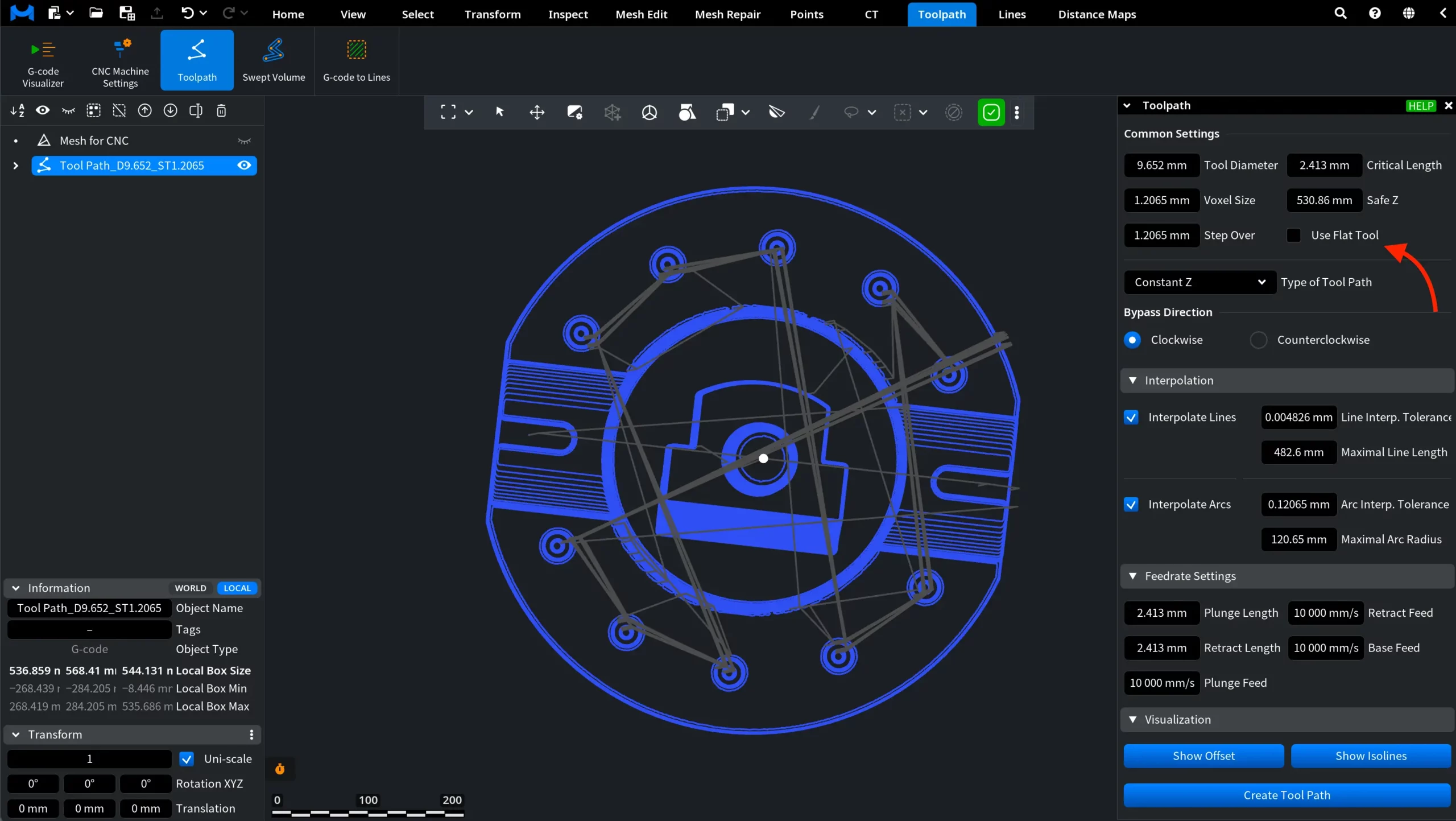
Here is how the same toolpath looks from above, with the source mesh hidden.
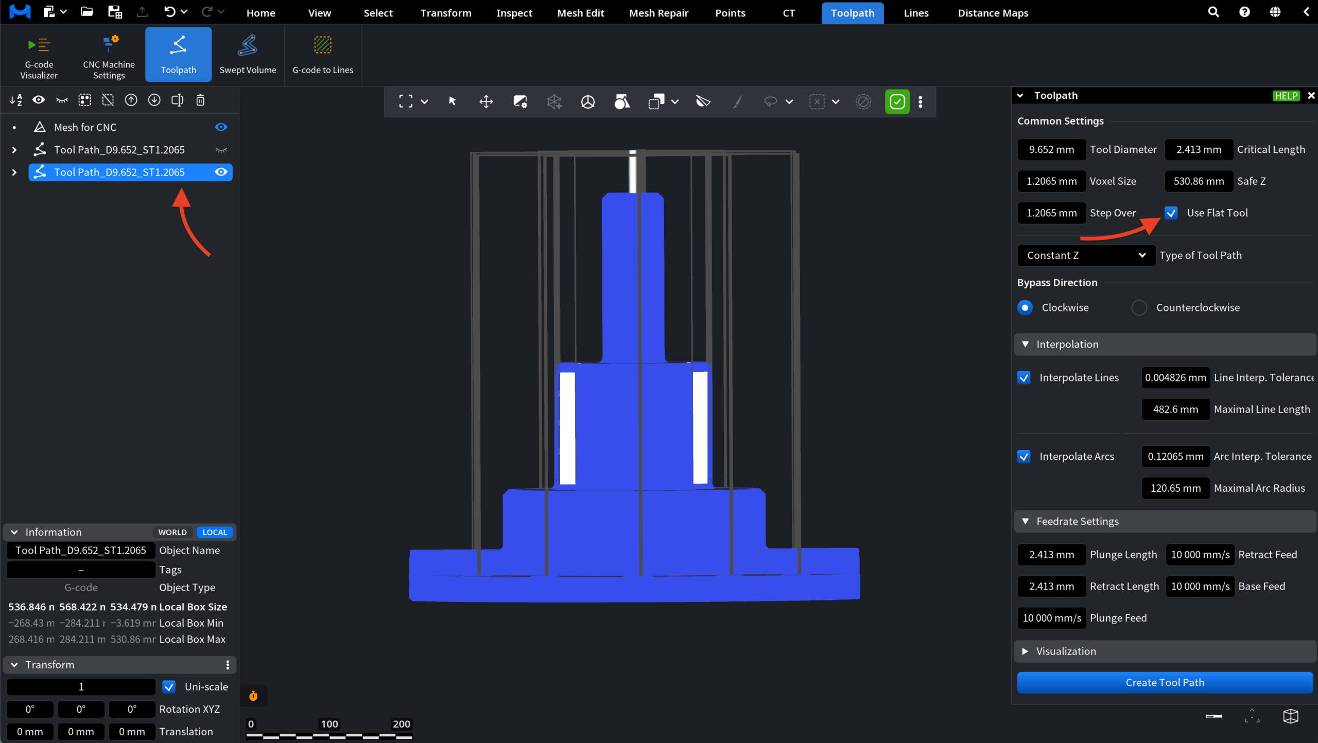
When Use Flat Tool is enabled, MeshInspector generates the toolpath for a flat milling tool. As a result, the generated passes are adapted to the flat tool mode while keeping the same general toolpath generation settings.
Here is how the same toolpath looks from above, with the source mesh hidden.
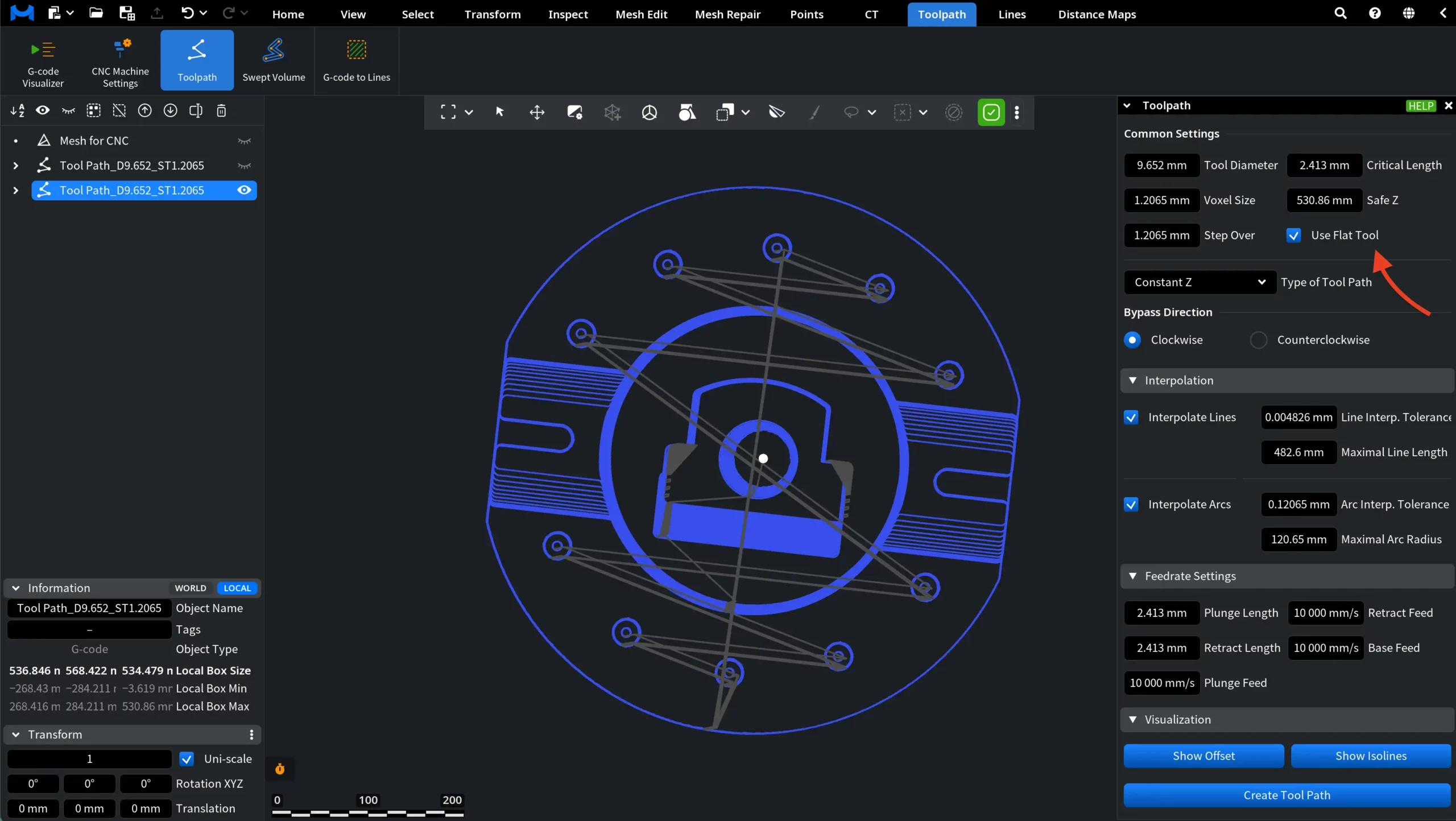
Enable Use Flat Tool when generating a path for a flat milling tool. Leave it disabled for other tool types.
After the toolpath is generated, the Visualization section becomes available and contains two buttons:
- Show Offset
- Show Isolines