Convert GLTF models to precise, printable STL files ready for manufacturing.


Watch our quick tutorial or read:
Compare GLTF to STL converters and find the best fit for your workflow.
|
MeshInspector
|
MeshInspector
|
Other Converters
|
|
|---|---|---|---|
| Speed |
Ultra-fast Local processing
|
Fast
|
Slow
|
| File Size Limits |
Unlimited
|
Unlimited
|
File size limit (50 MB)
|
| File Number Limits |
Unlimited
|
Unlimited
|
Usually single file only
|
| Folder Support |
Full folder import
|
Full folder import
|
Not supported
|
| Assembly Conversion |
Partial or full assembly
|
Partial or full assembly
|
Not supported
|
| Mesh Validation |
Integrated
|
Integrated
|
Not supported
|
| Auto Mesh Repair |
Advanced
|
Advanced
|
Not supported
|
| Mesh Repair Options |
Advanced
|
Advanced
|
Not supported
|
| Accuracy Control |
Full
|
Full
|
Not supported
|
| 3D Viewer |
Advanced
|
Advanced
|
Basic or no preview
|
| 3D Editor |
Advanced
|
Advanced
|
Not supported
|
| Security & Privacy |
100% Local
|
SSL + Auto-delete
|
Files often stored on servers
|
| Cross-Platform |
Windows, macOS, Linux
|
All devices
|
Web only, limited mobile UX
|
| Suitable for |
Professionals and engineers
|
Quick online conversions
|
Not recommended
|
Join thousands of engineers who trust MeshInspector for their 3D file conversion needs. Start converting today with no limits and professional results.
Powered by MeshInspector technology for reliable file conversion.
MeshInspector is a dependable solution for 3D specialists who need to convert GLTF files into the STL format. This walkthrough explains how to transform your GLTF model into a unified, well-structured, and ready-to-use single STL file using MeshInspector’s intuitive interface and efficient and UX-driven workflow.
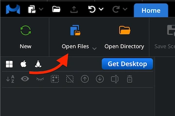
To take the first step in your GLTF-to-STL conversion, launch the MeshInspector program. Once the workspace opens, navigate to the ‘Home tab’ and click ’Open Files.’ Then, choose your GLTF model and allow MeshInspector to load it, preparing it for further processing and export.
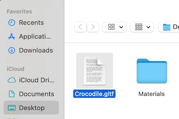
MeshInspector will open a file dialog for selecting your GLTF model. You may notice that GLTF files have a distinct structure. That is, they are based on JSON, which stores information about geometry, materials, and scene hierarchy. Click Browse, find your file, and confirm the selection to proceed.
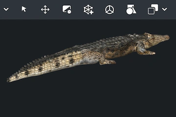
After your GLTF model is loaded, MeshInspector will render it directly in the main viewport. The object appears with its original textures, materials, and lighting — similar to the crocodile model shown here. On the left-hand side, the ’Scene Tree’ provides a structured view of all imported elements.
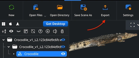
Now it’s time to convert your GLTF model into the desired format. In the Scene Tree, locate the object you wish to export. Right-click on it to select it for conversion, then choose ’Export’ from the context menu, as shown. This action opens the export dialog.
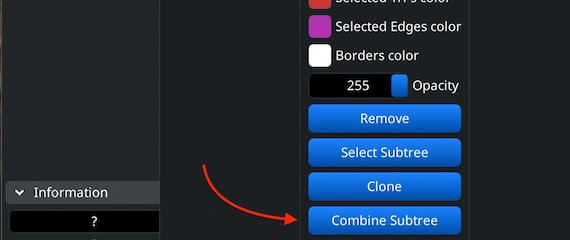
If your GLTF model contains several separate elements, you can merge them before exporting. In the Scene Tree, select all the parts to include, right-click, and choose ’Group.’ Then, right-click the created group and select ’Combine Subtree.’ This will fuse the elements.
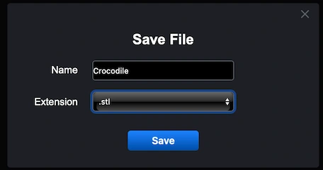
After selecting ’Export,’ a ’Save File’ dialog will open. Here, you can rename your file if necessary and expand the ’Extension’ dropdown menu. From the available options, choose .stl as the output format. Once everything is set, click ’Save.’ MeshInspector will begin converting your GLTF model into a single STL file.
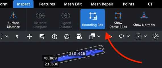
After the export finishes, it would be logical to verify that your model features correct proportions. Open the newly created .stl file and go to the ’Inspect’ tab. Then select ’Bounding Box.’ This tool will display your object’s current dimensions and spatial boundaries, helping you confirm that the scale and volume remain adequate.
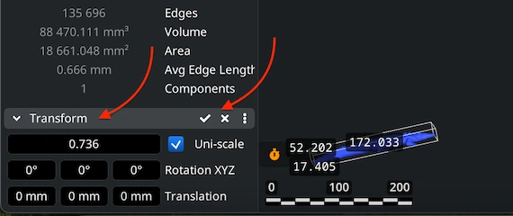
If your model appears oversized or undersized after inspection, visit the ‘Transform’ panel. There, try to Scale via the highlighted bar. When the proportions look right, confirm the adjustment by applying the changes through the checkbox. This ensures that your STL file will fit seamlessly into future 3D data and printing workflows.
100% Secure
No data leaves your device
sliced perfectly. much appreciated.
lifesaver thx 🙏
printed the game model successfully. Thanks!