Convert TIF image slices to ASC grids, extract pixel intensity values, set scaling parameters and export plain‑text files for further analysis.


Watch our quick tutorial or read:
Compare TIF to ASC converters and find the best fit for your workflow.
|
MeshInspector
|
MeshInspector
|
Other Converters
|
|
|---|---|---|---|
| Speed |
Ultra-fast Local processing
|
Fast
|
Slow
|
| File Size Limits |
Unlimited
|
Unlimited
|
File size limit (50 MB)
|
| File Number Limits |
Unlimited
|
Unlimited
|
Usually single file only
|
| Folder Support |
Full folder import
|
Full folder import
|
Not supported
|
| Assembly Conversion |
Partial or full assembly
|
Partial or full assembly
|
Not supported
|
| Mesh Validation |
Integrated
|
Integrated
|
Not supported
|
| Auto Mesh Repair |
Advanced
|
Advanced
|
Not supported
|
| Mesh Repair Options |
Advanced
|
Advanced
|
Not supported
|
| Accuracy Control |
Full
|
Full
|
Not supported
|
| 3D Viewer |
Advanced
|
Advanced
|
Basic or no preview
|
| 3D Editor |
Advanced
|
Advanced
|
Not supported
|
| Security & Privacy |
100% Local
|
SSL + Auto-delete
|
Files often stored on servers
|
| Cross-Platform |
Windows, macOS, Linux
|
All devices
|
Web only, limited mobile UX
|
| Suitable for |
Professionals and engineers
|
Quick online conversions
|
Not recommended
|
Join thousands of engineers who trust MeshInspector for their 3D file conversion needs. Start converting today with no limits and professional results.
Powered by MeshInspector technology for reliable file conversion.
Converting grayscale rasters into numeric 3D datasets is a common requirement in terrain modeling, CAD/CAM workflows, simulation tasks, and other processes that rely on heightfields. MeshInspector provides an exact and reproducible way to perform this operation, i.e., conversion from TIF files to ASC, inside a single program you can work with online and offline. Our program allows users to interpret grayscale values as height and export the result as a single ASC file suitable for CAD, GIS, simulation, or terrain-generation pipelines. Below is a detailed and step-by-step guide that explains how to load your TIF, adjust conversion parameters, and produce a clean ASC dataset.
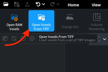
To start working with your TIF files in the MeshInspector program, open the ’CT’ tab. After that, click on ’Open Voxels From TIFF.’ This command will allow you to load a set of TIF images as a single volumetric dataset. This, in turn, will enable you to preview and change the eventual result.
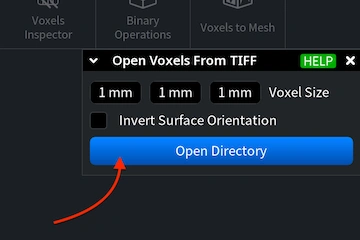
A panel appears. Here, you can define the voxel size for the dataset. You can either type in the desired values or adjust them by dragging horizontally over each field. Below the voxel size fields, you can enable ‘Invert Surface Orientation.’ Once the settings are finalized, click ’Open Directory.’
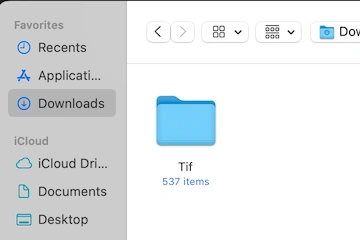
Clicking ‘Open Directory’ launches the file-selection dialog. Our program processes TIFs as volumetric stacks. Thus, you must choose a folder containing multiple TIFs, a single file is not sufficient. Navigate to the directory that stores your slice sequence, select it, and then click 'Upload.'
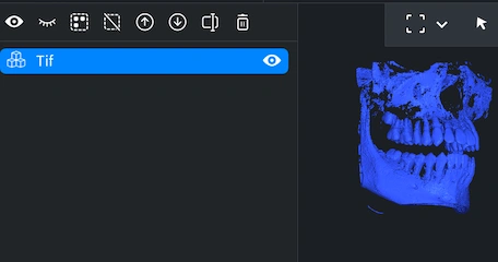
Once uploaded, the TIF appears as a single object in your Viewport and in the Scene Tree on the left. MeshInspector treats the raster as a heightmap-ready dataset that can be inspected just like any other 3D or volumetric object. Here is what you can do next. Rist, rotate the view by dragging with the left mouse button (or using a one-finger touchpad gesture). Pan by holding the right mouse button or sliding two fingers on a touchpad. Zoom with the mouse wheel or a pinch gesture. To tilt the camera, hold Ctrl and drag with the left mouse button.
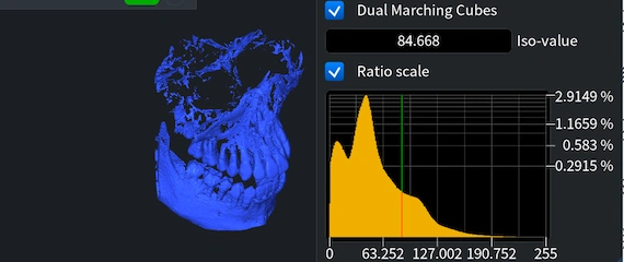
When your TIF represents volumetric data, you can fine-tune which density levels are turned into visible geometry by adjusting the ISO-value. When you click ‘Change ISO,’ under ‘CT’ MeshInspector displays a histogram of voxel intensities. The vertical marker on the histogram corresponds to the current ISO threshold. Click anywhere on the histogram to set a new ISO-value. The 3D preview on the left refreshes in real time. You can also switch between surface extraction algorithms, ‘Dual Marching Cubes’ and ’Standard Marching Cubes.’ Enable ’Ratio scale’ if you want the histogram to be presented regardless of absolute voxel counts.
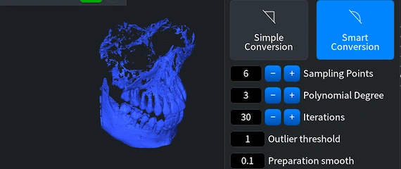
Now, we take another step on the route to a successful conversion from TIF files to ASC. Our initial voxel-based TIF must become a mesh. For that, under ‘CT’, click ‘Voxels to Mesh.’ Two options will be available: 'Simple Conversion' and 'Smart Conversion.' The second applies an additional refinement stage that improves the surface by sampling points around each vertex and fitting them to a local polynomial, including ‘Sampling Points,’ ‘Polynomial Degree,’ ‘Iterations,’ ‘Outlier Threshold,’ etc. Whatever your choice might be, you can always tick the ‘Preserve Voxel Object’ box to keep the voxel dataset in the Viewport. Click ‘Convert’ to initiate the process.
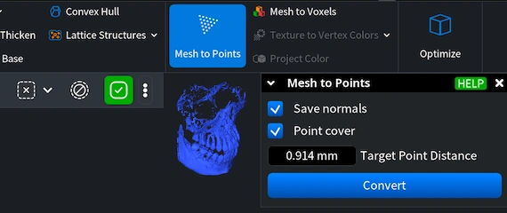
Our next step is to turn the mesh into a point cloud. Select the mesh in the ’Scene Tree,’ open ’Mesh Edit,’ and click ’Mesh to Points.’ A small panel appears with several parameters. Save normals, if enabled, stores per-point normals derived from the mesh surface. Point cover ensures uniform point distribution across the surface; when you enable this option, an additional field, ‘Target Point Distance,’ appears. This value defines the spacing between points and therefore the density of the generated cloud. After choosing your settings, click ’Convert’ to create the point-cloud object.
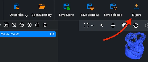
The final step of our TIF-to-ASC conversion workflow is to export our processed dataset in the ASC format. With the point cloud selected in MeshInspector’s ‘Scene Tree,’ go to the top toolbar, under the ‘Home’ tab, and click ‘Export.’ A file-format dropdown will appear. From this list, among all other alternatives, choose ASC format. The MeshInspector program for 3D data will then prompt you to specify a filename and destination. After selecting the location, click ‘Save.’ As a result, our solution will then generate a standard single .asc file you can work with later.
100% Secure
No data leaves your device