The Toolpath tab is for checking CNC milling programs. You can open an existing G-code program, or build a toolpath for a mesh, then watch the tool move along it, simulate the milling of a work piece and build the volume the tool sweeps. This guide explains how G-code gets into MeshInspector, the usual workflow, the tool shapes and what the tools cannot do.

G-code in MeshInspector
A CNC program becomes a G-code object in the scene. There are two ways to get one:
- Open a file. Click Open Files and pick a program with the extension .gcode, .nc or .txt.
- Build a toolpath. Select one mesh and run Toolpath. The result is a G-code object named after the tool diameter and step, for example Tool Path_D0.2_ST0.025.
A G-code object is a program, not geometry: the tools of the Toolpath tab read it command by command. To turn it into ordinary polylines, use G-code to Lines.
The Workflow
- Prepare the part. Open the mesh of the part and turn it so that the side to mill faces +Z: the tool always comes from above.
- Build the toolpath. Select the mesh and click Toolpath › Toolpath. Choose the path type and the tool, then build the path. See Toolpath.
- Check the program. Select the G-code object and click Toolpath › G-code Visualizer: step through the moves, animate the tool and simulate the milling of a work piece. See G-code Visualizer.
- Check what the tool removes. Click Toolpath › Swept Volume to build the volume the tool sweeps along the path, and compare it with the part. See Swept Volume.
If the program uses rotary axes or you want the simulator to match your machine, set it up first in CNC Machine Settings.
Which Tool Do I Need?
| I want to… | Tool |
|---|---|
| See a G-code program, step through its moves, animate the tool and simulate milling | G-code Visualizer |
| Set up the simulated machine: rotary axes, their order and limits, idle feed rate, home position | CNC Machine Settings |
| Build a toolpath for a mesh | Toolpath |
| Build the volume the tool sweeps along a G-code program or a polyline | Swept Volume |
| Turn a G-code program into polylines | G-code to Lines |
Tool Shapes
G-code Visualizer and Swept Volume share one tool library. Open the Tool Mesh list in either tool to pick a tool:
- Default: a simple cylinder sized to the program;
- a tool you created before; MeshInspector keeps your tools between sessions;
- <Create Tool>: opens the Create Tool window, see below;
- <New Tool from File>: loads a tool shape from a mesh file;
- <New Tool from exist Mesh>: uses a mesh of the scene as the tool.
Remove deletes the selected tool from the library.
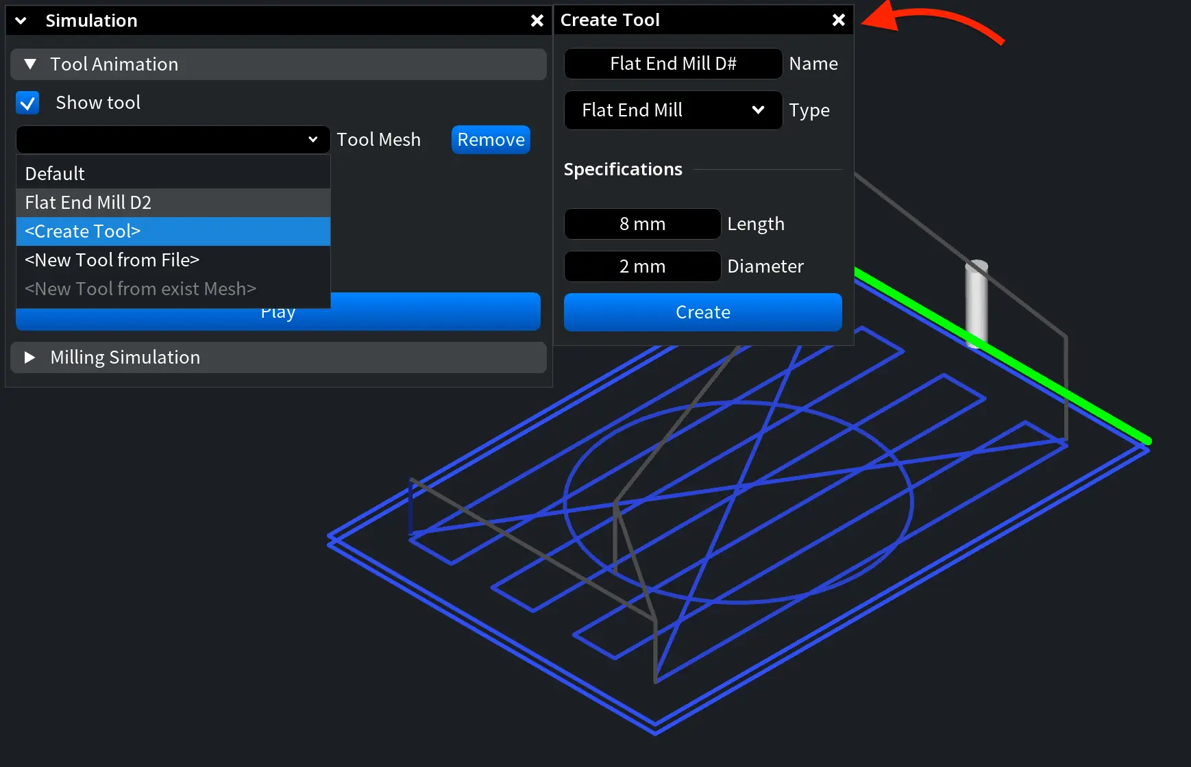
In the Create Tool window, enter a Name and choose the Type. Every type has a Length and a Diameter; some types add one or two parameters:
| Type | Parameters | Shape |
|---|---|---|
| Flat End Mill | Length, Diameter | A cylinder with a flat end. |
| Ball End Mill | Length, Diameter, Cutter Radius | A ball-shaped end; Cutter Radius is half the Diameter, changing one changes the other. |
| Bull Nose End Mill | Length, Diameter, Cutter Radius | A flat end with rounded corners; Cutter Radius is the corner radius, up to half the Diameter. |
| Chamfer End Mill | Length, Diameter, Cutting Angle, End Diameter | A conical end; Cutting Angle from 0° to 180°, End Diameter from 0 (a sharp tip) up to the Diameter. |
The window starts with a Flat End Mill of Length 8 and Diameter 2. Click Create, and the new tool appears in the Tool Mesh list.
Limits
- No G-code export. MeshInspector opens G-code but does not write it: Export is not available for a G-code object. Use the Toolpath tab to build, study and check toolpaths, not to produce the program for your machine.
- Axes. Toolpath builds 3-axis programs: moves in X, Y and Z with the tool pointing along Z. The G-code Visualizer also reads the rotary axes A, B and C when you turn them on in CNC Machine Settings.
- Simulation accuracy. The milling simulation works on a voxel grid: a smaller Voxel Size gives a finer result and takes longer.


