Inspect GCODE files with MeshInspector’s GCODE Viewer to visualize toolpaths by layer, spot print or CNC issues, and refine machine settings.


Watch our quick video or read:
MeshInspector has a range of tools for CNC machining and 3D printing. It works as a gcode viewer, simulator, and editor. MeshInspector is like an expert in simulating g-code, a viewer for gcode online, and a precise gcode editor. It makes CNC interaction easier and more accurate.
|
MeshInspector
|
MeshInspector
|
Other STL Readers
|
|
|---|---|---|---|
| Perfomance |
Ultra-fast (GPU acceleration)
|
High
|
Slow
|
| Batch Import |
Unlimited
|
Unlimited
|
Single file
|
| File Limits |
Unlimited
|
Unlimited
|
~100 MB
|
| Measurement Tools |
Advanced
|
Advanced
|
Limited
|
| Metadata Support |
Full
|
Full
|
Not supported
|
| Scaling |
Advanced
|
Advanced
|
Not supported
|
| 3D Editor |
Advanced
|
Advanced
|
Not supported
|
| Screenshots |
Advanced
|
Advanced
|
Limited
|
| Supported Files |
STL (ASCII/Binary), OBJ, PLY, GLTF
|
STL (ASCII/Binary), OBJ, PLY, GLTF
|
STL (Binary)
|
| Export |
Multiple formats
|
Multiple formats
|
Not supported
|
| Security & Privacy |
Corporate security + Local storage
|
SSL + Auto-delete
|
Server-side storage
|
| Cross-Platform |
Windows, macOS, Linux
|
All devices
|
Web only, poor mobile UX
|
| Suitable for |
Professional & industrial use
|
Quick viewing & sharing
|
Not recommended
|
Join thousands of engineers who trust MeshInspector for their 3D file conversion needs. Start converting today with no limits and professional results.
Explore the full MeshInspector ecosystem — advanced 3D model viewers and converters for engineers, designers, and makers.
3D professionals need tools that are capable of opening and assessing GCODE files. These contain machine instructions that define how 3D printers move, extrude material, change layers, and form final objects. As long as GCODEs serve as the ‘blueprint’ for printing processes, such a viewing tool must deliver accuracy, speed, and stable performance on any OS. MeshInspector addresses this very need by offering a free and cross-platform read GCODE file program. It allows one to inspect paths both offline through the downloadable app and online through the browser. The MeshInspector program loads trajectories quickly, displays extrusion and travel moves clearly. As such, it helps users verify layer height, perimeter quality, and overall toolpath logic before the printing operations begin.
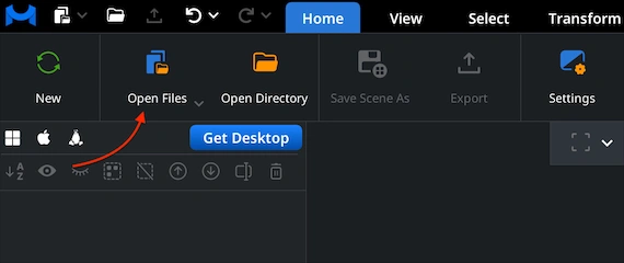
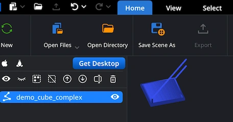
Under the ’Home’ tab, click ’Open Files.’ This option lets you load your GCODE file into MeshInspector for inspection. After you select the file, our viewer imports the full toolpath and prepares it for visualization, regardless of how dense the extrusion data is or how many layers the print contains.
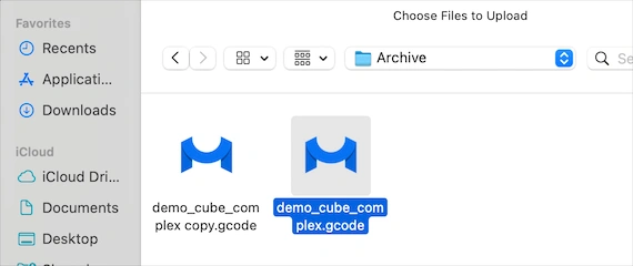
Click ’Browse.’ After that, navigate to the folder where your NC file is stored. Then either double-click the file or confirm the selection with Upload. The MeshInspector program for reading NC files can also open entire folders containing multiple operations, which is useful when a workflow is split into components.
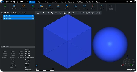
After the GCODE file is loaded, its toolpath appears. You are free to examine it from any angle. Rotate the GCODE view by dragging with the left mouse button or using a one-finger touchpad gesture. Pan the scene by holding the right mouse button or sliding two fingers on a touchpad. Zoom in or out with the mouse wheel or a pinch gesture. To tilt the view, hold Ctrl and drag with the left mouse button. These controls, taken together, allow you to review layer transitions, extrusion paths, travel lines, and overall print geometry.
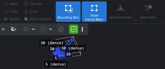
Under the ’Inspect’ tab, you can press ’Bounding Box’ or ’Show Dense Box’ to view the physical dimensions of your toolpath. ‘Bounding Box’ displays an axis-aligned box that encloses the selected object. It gives you a quick and clean understanding of your model’s outer limits. ‘Show Dense Box’ reveals the minimal bounding box that tightly wraps the object. This easily accessible option is useful when the print contains angled geometry, overhangs, or tilted paths.
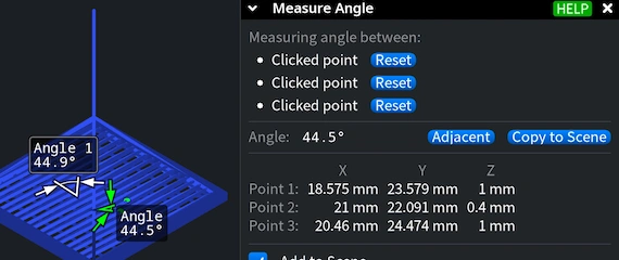
MeshInspector allows you to inspect individual features of a GCODE toolpath with precision. To measure an angle, open the ’Measure Angle’ tool from the ’Inspect’ tab. Click three points directly on the toolpath. As soon as you place the third point, the MeshInspector program to read GCODE files quickly calculates the angle and displays it both in the viewport and in the measurement panel, which is convenient when you need to double-check and validate anything of importance to you.
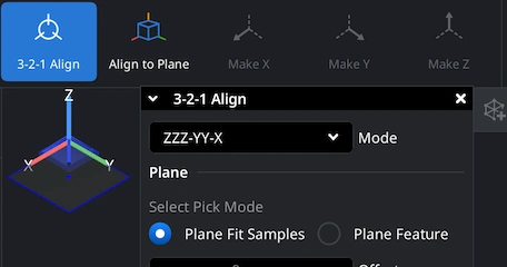
The ‘3-2-1 Align’ under ‘Transform’ tool makes it possible for users to position their GCODE models precisely within the coordinate system. This method is commonly used in 3D workflows to define a stable orientation based on three reference steps: a primary plane (3 points), a secondary direction (2 points), and a final axis constraint (1 point). In MeshInspector, this workflow allows you to correct toolpaths that were exported in an unexpected orientation or to prepare them for comparison, analysis, or downstream processing.
100% Secure
No data leaves your device
Integrate real-time 3D visualization, mesh analysis, and measurement tools directly into your applications with MeshLib SDK.
Modern UI — built with Dear ImGui: ribbon interface, scene tree, view cube, and measurement tools.
Order-Independent Transparency (OIT) — realistic rendering of transparent materials.
Customizable Interaction — support for mouse, keyboard, touch gestures, and SpaceMouse devices.
Plugin Architecture — extend the Viewer with your own tools and workflows.