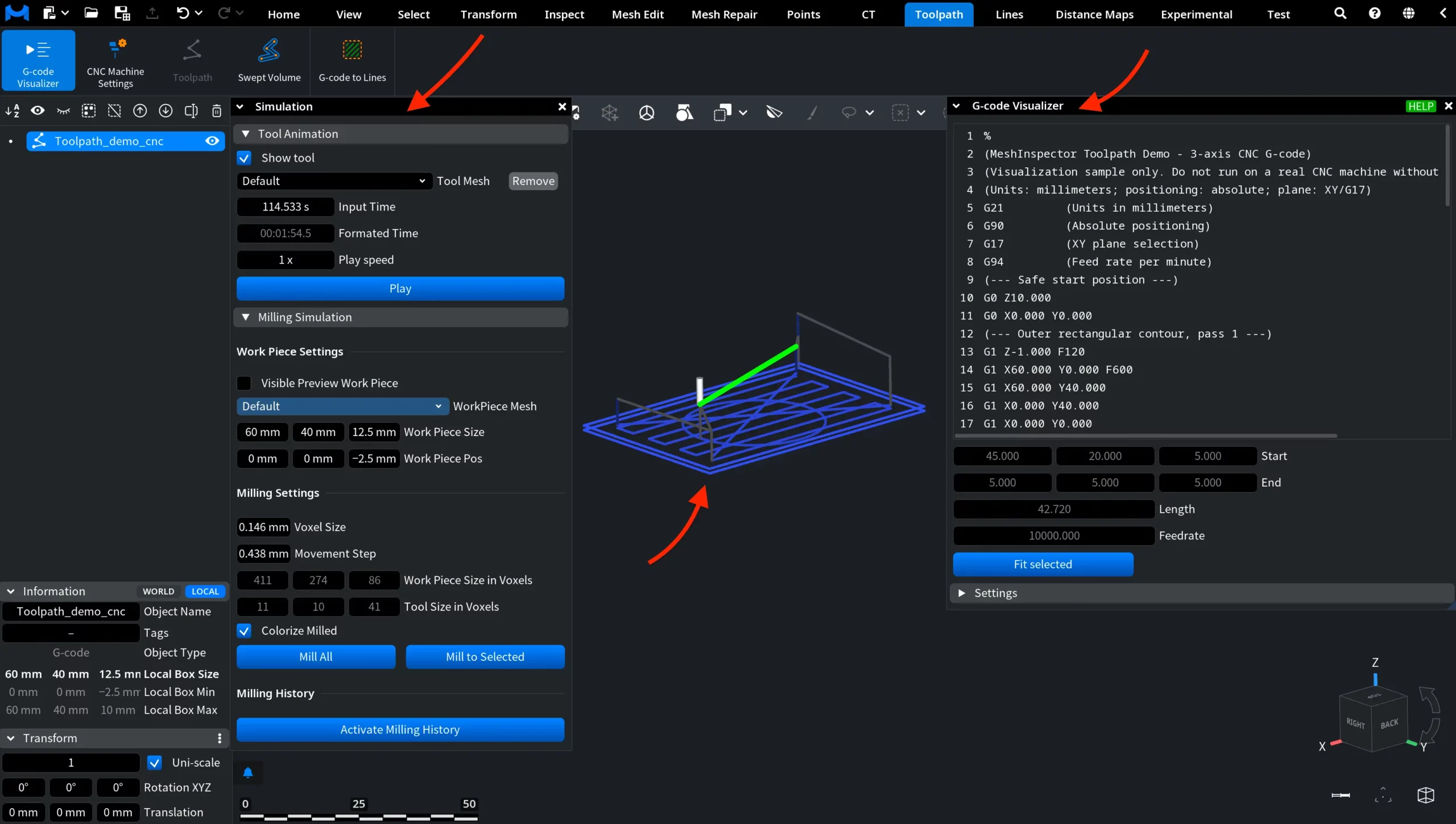
A G-code object is a CNC program in the scene. MeshInspector reads the G-code commands line by line and draws the path of the cutting tool in 3D. In the app this object type is called G-code; we also call it a toolpath. You need it to check a CNC program before it goes to the machine: see where the tool moves, play the cut step by step, simulate milling of a workpiece, or build the volume the tool sweeps.
A G-code object keeps the text of the program. It looks like a polyline, but each piece of its path remembers the G-code line it came from and its feedrate.
How a G-code object looks
- Scene tree: the icon is three dots joined by lines, like a path through points.
- Viewport: cutting moves are drawn in the object color. With Feedrate as Gradient on (the default), faster moves are brighter. Rapid (idle) moves are gray.
- Information panel: Object Type is G-code, and the panel shows the bounding box of the path: Local Box Size, Local Box Min and Local Box Max (or the World values).
- Inspect › Object Info also lists the number of path vertices and the total length of the path.
Open a G-code file
Open the file with Home › Open Files, or drag it into the MeshInspector window. Files with these extensions open as a G-code object:
| Extension | File type in the Open Files dialog |
|---|---|
| .gcode | G-code |
| .nc | Numerical Control |
| .txt | Text file |
A .txt file always opens as G-code. If your .txt file is a list of X Y Z point coordinates, rename it to .xyz to open it as a point cloud.
MeshInspector reads these commands and skips the others:
| Command | What it does in MeshInspector |
|---|---|
| G0, G1 | Rapid move, linear cutting move |
| G2, G3 | Arc clockwise, counterclockwise (I, J, K or R) |
| G17–G19 | Arc plane XY, ZX or YZ |
| G20, G21 | Inches, millimeters |
| G90, G91 | Absolute, relative coordinates |
| G28 | Return to the home position |
| G50, G51 | Scaling off, on |
| A, B, C | Rotary axes, as set in CNC Machine Settings |
| F | Feedrate of the move |
Create a toolpath from a mesh
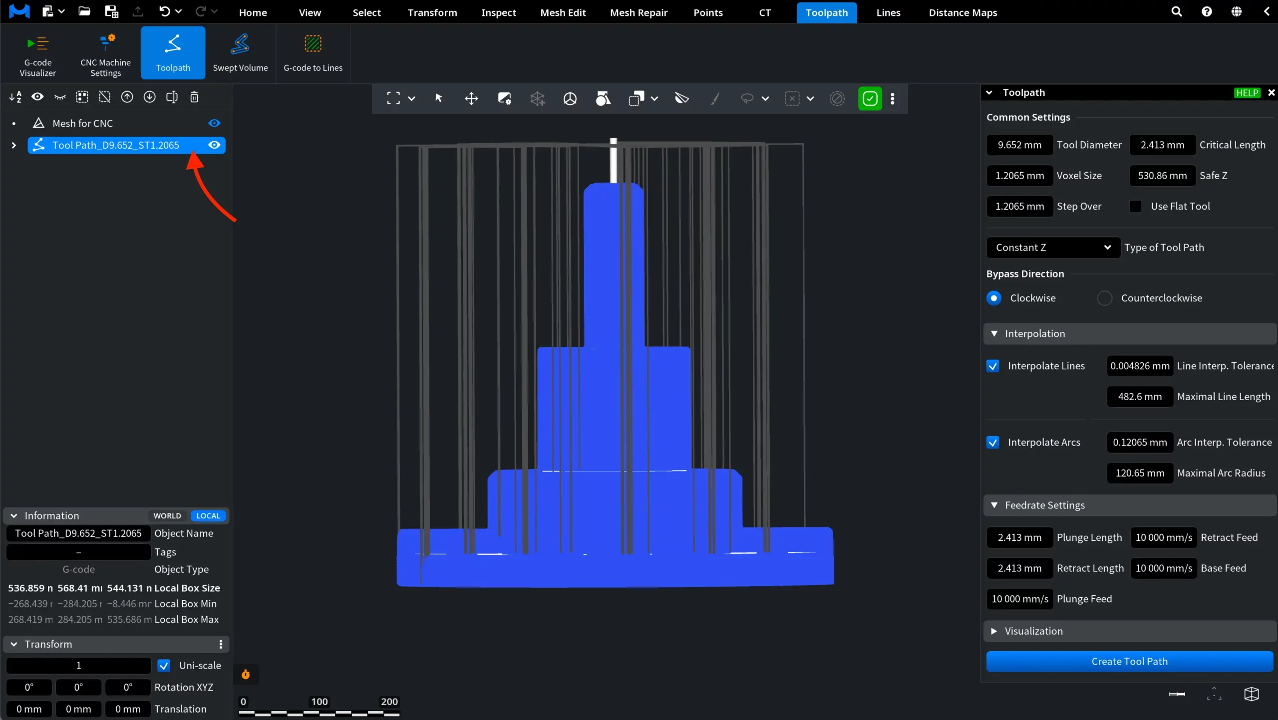
Toolpath › Toolpath builds a toolpath for one selected mesh. The result is a new G-code object named Tool Path… in the Scene tree, with a Tool mesh inside it, so every tool below works with it as with an opened file. The Toolpath tool needs the Professional plan. Settings and steps are in the Toolpath article.
What you can do with a G-code object
Select exactly one G-code object in the Scene tree. The tools of the Toolpath tab then become available:
| Tool | What it does |
|---|---|
| G-code Visualizer | Lists the program line by line, highlights the move of the selected line, plays the tool along the path and simulates milling of a workpiece. See G-code Visualizer. |
| CNC Machine Settings | Sets the rotary axes A, B and C, their order and limits, the idle feedrate and the home position used to read the program. See CNC Machine Settings. |
| Swept Volume | Builds a mesh of the space the tool occupies along the path; it also works on a polyline. See Swept Volume. |
| G-code to Lines | Turns the G-code object into a polyline, with or without the idle moves (Professional plan). See G-code to Lines. |
You can also move and rotate a G-code object like any other object, for example to place it over the part in the scene.
Save a G-code object
- Home › Save Scene or Save Scene As stores the G-code object, together with its program text, in a MeshInspector scene file (.mru). Open the scene later to continue where you stopped.
- Export does not save G-code objects: it works for meshes, point clouds, polylines, distance maps and voxel volumes. MeshInspector does not write G-code files.
- To save the path geometry for other software, run G-code to Lines and export the polyline as .mrlines, .pts, .ply or .dxf.


